Hello! Welcome to the next lesson in our Embedded Interview Preparation Bootcamp.
In our last session, we mapped out the internal geography of an ELF executable, identifying the key sections like .text, .data, and .bss. We noted that the .data and .bss sections, which live in RAM, require preparation before our application logic can run. This preparation is handled by "startup code."
Today, we will dissect that very startup code. We'll answer the classic and crucial interview question: "What happens before main()?". Tracing the execution flow from the moment of processor reset all the way to the first line of main is a fundamental skill that demonstrates a deep understanding of how hardware and software truly connect in an embedded system.
Our learning outcome for this lesson is to: Explain the sequence of startup code execution before main(): vector table setup, copying initialized data, and zeroing BSS.
The Journey from Power-On to main()
The startup process is a well-defined sequence of events. At a high level, the processor wakes up, finds the starting point of your code using a special map, performs essential hardware and memory initializations, and only then transfers control to your main function.
This diagram provides a great visual summary of the entire journey.

Let's break down each of these steps in detail.
Step 1: The Spark of Life – Processor Reset and the Vector Table
When an ARM Cortex-M processor is powered on or reset, it doesn't magically know where your main function is. Instead, its behavior is hardwired. It performs two critical fetches from a specific location in memory: the Interrupt Vector Table.
By default, this table is located at address 0x00000000. The processor reads two 32-bit values:
- Address
0x00: The initial value for the Main Stack Pointer (MSP) register. The stack must be set up before any function calls can be made. - Address
0x04: The address of the Reset Handler. This is the entry point of your program—the very first instruction the CPU will execute.
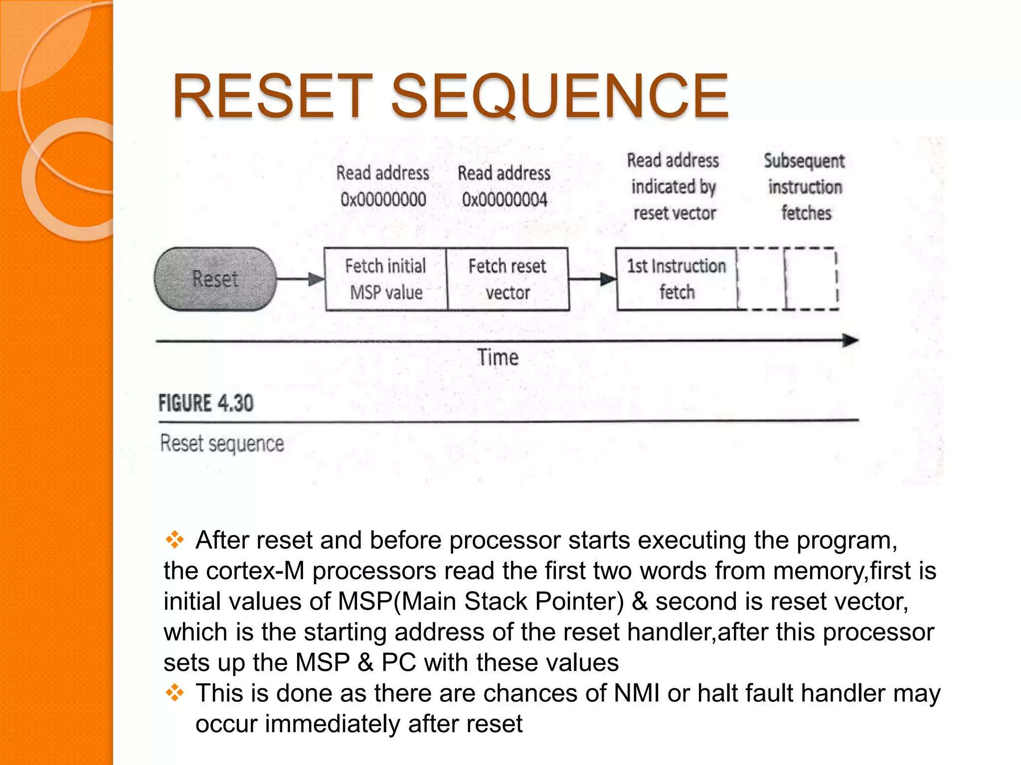
This Reset_Handler is the beginning of the startup code provided by your toolchain or SDK. The entire sequence—from reset to the final call to main—is often contained in a single assembly file, commonly named startup_McuName.s.
To see this process in a real-world context, the following video segment steps through the very beginning of a debug session, showing how the processor state (SP and PC) is initialized directly from the vector table.
#13 Startup Code Part-1: What is startup code and how the CPU gets from reset to main?
The video '#13 Startup Code Part-1' from Quantum Leaps, LLC provides an excellent look at the hardware-level startup sequence on an ARM Cortex-M device.
Please watch from 16:47 to 19:18. Focus on how the narrator uses the debugger to inspect the memory at address 0 and demonstrates that the values stored there are used to initialize the SP and PC registers. This directly visualizes the concept shown in the diagram above.
Step 2: Inside the Reset_Handler – Preparing the C Runtime
The Reset_Handler is your program's true entry point. Its primary responsibility is to prepare the C runtime environment so that main can execute as expected according to the C standard. This involves two critical memory initialization tasks that we discussed in the last lesson.
Task 1: Copying Initialized Data (the .data section)
Any global or static variable you declare with an initial value, like int global_counter = 42;, resides in the .data section.
- The initial value (
42) is stored in the non-volatile Flash memory as part of your program's binary image. - The variable itself must live in RAM so it can be modified at runtime.
The startup code bridges this gap. It copies a block of bytes containing all the initial values from a location in Flash to the .data section's final destination in RAM. The linker provides the source and destination addresses via special symbols (often _sidata, _sdata, _edata).
Task 2: Zeroing Uninitialized Data (the .bss section)
Any global or static variable declared without an initial value, like uint8_t rx_buffer[1024];, resides in the .bss (Block Started by Symbol) section.
The C standard guarantees that such variables are initialized to zero. However, at power-on, RAM contains random garbage. To fulfill the C standard, the startup code must explicitly write zeros to the entire memory region allocated for the .bss section. The linker provides the start and end addresses for this region (often _sbss and _ebss).
As we saw last lesson, this is a crucial optimization: the executable file only needs to store the size of the .bss section, not a large block of zeros, thus saving precious Flash space.
A Practical Demonstration
Seeing is believing. The next video segment provides a fantastic walkthrough using a debugger to show these two memory initialization loops in action.
#13 Startup Code Part-1: What is startup code and how the CPU gets from reset to main?
Continuing with the Quantum Leaps video, we'll now see the core logic of the startup code as it prepares the RAM.
Please watch from 08:24 to 15:41. This is the most critical part of the lesson. Introducing Initialized Data (08:24 - 12:52): Observe how adding initialized variables to the C code causes the linker to create a .data section in RAM and a corresponding 'Initializer bytes' section in ROM (Flash). Stepping Through the Code (12:52 - 15:41): Pay close attention as the debugger steps through the __iar_data_init3 function. First, you will see it loop through the .bss section, writing zeros. Then, you will see it loop again, copying bytes from Flash to the .data section in RAM. The narrator uses the memory view to make this process clearly visible.
For a clear, text-based reference, the article "From Zero to main()" shows a minimal C implementation of these same initialization loops inside a Reset_Handler. This is a common way to implement startup code without resorting to pure assembly.
From Zero to main(): Bare metal C - Memfault Interrupt
The blog post 'From Zero to main(): Bare metal C' on the Memfault Interrupt blog provides a concise, C-based implementation of a Reset_Handler.
Read the section 'Writing a Reset_Handler'. Focus on the two for loops that implement the BSS zeroing and the DATA copy. This reinforces what you saw in the video with a clean code example.
Step 3: Early Hardware Configuration
Besides memory initialization, the startup code often performs very early, low-level hardware setup by calling a function typically named SystemInit(). This function is called before the .data and .bss sections are initialized, so it must not rely on any global variables.
Typical tasks for SystemInit() include:
- Configuring System Clocks: Switching from a slow internal oscillator to a faster external crystal and configuring PLLs (Phase-Locked Loops). This is done early so the rest of the startup code (and the application) runs at full speed.
- Enabling the FPU: If the processor has a Floating-Point Unit, it often needs to be explicitly enabled before any floating-point math can be performed.
- Applying Silicon Errata Workarounds: Sometimes chips have known bugs (errata) that require specific registers to be configured at boot to ensure correct operation.
This call is a critical hook for tailoring the hardware environment before any application code runs.
Step 4: The Final Jump to main()
Once the C runtime environment is fully prepared and initial hardware configuration is done, the startup code's final task is simple: it makes a function call to main().
// ... after BSS zeroing and DATA copy ...

// Finally, call the application's entry point
main();

// In case main() ever returns, trap the CPU in an infinite loop
while(1) {
    // This should never be reached
}
The infinite loop after the call to main() is a defensive programming practice. In a bare-metal embedded system, main should never return. If it does, it means the program has likely run off into an undefined state. This loop prevents the processor from continuing to execute code from whatever random memory location follows the startup routine.
Conclusion
You have now traced the complete path from a processor reset to the execution of your application code. This is not just an academic exercise; understanding this sequence is vital for debugging low-level problems, optimizing boot time, and correctly managing memory in any bare-metal system.
Key Takeaways:
- Execution does not start at
main. It starts at theReset_Handleraddress found in the vector table. - The processor is hardwired to find the vector table at a specific address on reset, from which it loads the initial stack pointer and the
Reset_Handleraddress. - The primary jobs of the startup code are to prepare the C runtime environment:
- Copying
.data: Initial values are copied from Flash to RAM. - Zeroing
.bss: The uninitialized data area in RAM is filled with zeros.
- Copying
- The startup code also typically calls a
SystemInit()function for early clock and hardware configuration. - The final step of the startup sequence is the call to
main().
Preview of the Next Lesson:
Today, we saw the startup code using linker-defined symbols like _sdata, _edata, _sbss, and _ebss to know where memory sections are located. But who decides where those sections go? The answer lies in the linker script. In our next lesson, we will learn how to write and modify linker scripts to take full control over your program's memory layout, a powerful skill for any embedded engineer.