Hello! Welcome to the next lesson in our Embedded Interview Preparation Bootcamp.
In our last session, we demystified the linking process, focusing on how the linker resolves symbols (using strong vs. weak rules) and relocates code by patching addresses. We established that the linker's ultimate job is to combine multiple object files into a single executable.
Today, we'll examine the structure of that final executable file. The linker doesn't just throw everything together; it meticulously organizes code and data into standardized sections. Understanding this organization is fundamental for memory-constrained embedded systems, as it allows you to analyze and optimize your program's memory footprint. This is a topic that interviewers at companies like AMD, Nvidia, and Qualcomm expect experienced engineers to know cold.
Our learning outcome for this lesson is to: Identify and explain ELF sections (.text, .data, .bss, .rodata, .plt, .got) and their roles in memory layout.
Sections vs. Segments: Two Views of a Program
Before diving into specific sections, it's crucial to understand a key distinction in the Executable and Linkable Format (ELF): the difference between sections and segments.
- Sections: These are logical divisions of the file that matter during the linking phase. They group related data, such as executable code (
.text) or uninitialized variables (.bss). The linker works with sections. - Segments: These describe how the file's contents should be loaded into memory at run-time. The operating system's loader works with segments. A segment typically contains one or more sections and has associated memory permissions (e.g., read-only, read-write, execute).
The following video provides an excellent, quick explanation of this critical difference.
In-depth: ELF - The Extensible & Linkable Format
The video 'In-depth: ELF - The Extensible & Linkable Format' by stacksmashing clearly distinguishes between sections (for linking) and segments (for runtime).
Please watch from 00:39 to 01:58. Focus on the core idea: 'Segments are basically exclusively used at runtime, while sections are almost exclusively used at link time!'
This image provides a helpful visual model of how sections are grouped into loadable segments for execution.

With that distinction in mind, let's explore the most important sections you'll encounter.
The Core Data and Code Sections
Most of a program's code and data falls into one of four fundamental sections. A deep understanding of what goes where, and the implications for Flash and RAM usage, is a hallmark of a senior embedded engineer.
| Section | Content | Typical Memory | Permissions | Key Characteristic |
|---|---|---|---|---|
| .text | Executable machine code instructions. | Flash/ROM | R-X |
Contains the logic of your program. Read-only and executable to prevent accidental modification. |
| .rodata | Read-only data (e.g., const variables, string literals). |
Flash/ROM | R-- |
Placed in non-volatile memory to save RAM and ensure constants cannot be altered. |
| .data | Initialized global and static variables. | RAM | RW- |
Consumes both Flash (to store initial values) and RAM (for the runtime variable). Copied to RAM by startup code. |
| .bss | Uninitialized global and static variables. | RAM | RW- |
Consumes only RAM. The executable just stores its size; the startup code zeros this memory region before main(). |
The distinction between .data and .bss is particularly vital in embedded systems.
int initialized_var = 42;goes into.data. The value42must be stored in the Flash and copied to RAM at boot.int uninitialized_var;goes into.bss. The executable only needs to record that 4 bytes of RAM should be zeroed out at boot. This saves valuable Flash space.
A Practical Demonstration
Theory is good, but seeing it in action is better. The next video walks through a C code example, showing exactly where different types of variables are placed in memory. It uses a debugger, a linker script, and a map file—all standard tools in embedded development.
How Microcontroller Memory Works | Embedded System Project Series #16
The video 'How Microcontroller Memory Works' by Artful Bytes is a fantastic practical guide that connects C code directly to the memory layout and ELF sections.
Please watch from 03:15 to 23:12. This is a detailed walkthrough, so pay close attention to how the presenter uses different tools: Code Analysis (07:40 - 13:04): Notice how he defines global, const, uninitialized, local, and static variables and predicts where each will go. Linker Script (13:04 - 15:02): See how the linker script explicitly maps sections like .text, .data, and .bss to physical memory regions (Flash and RAM). Map File & Debugger (15:43 - 20:49): Follow along as he uses the linker-generated map file to find the addresses of the sections and then uses the debugger's memory browser to verify that the variables are exactly where they are supposed to be. Startup Code (22:10 - 23:12): The video concludes by showing that the startup code (in a section called .cinit) is responsible for initializing the .data and .bss sections before main() is ever called.
This practical demonstration solidifies the roles of .text, .rodata, .data, and .bss and introduces the essential tools—linker scripts and map files—that you use to control and verify memory layout. The article "Analyzing the Linker Map file" is an excellent companion resource that dives deeper into interpreting these files.
Analyzing the Linker Map file with a little help from the ELF...
To further explore the tools from the video, this article from embeddedrelated.com explains how to interpret linker map files and use binutils to analyze memory usage.
Skim through this article to reinforce your understanding. Focus on: 'The memory map of a basic program': This section provides another clear explanation of the roles of DATA and BSS and the job of the crt0 startup code. 'Interpreting a Map File': See how the map file gives a breakdown of memory contributions. 'Hunting down statics with Some ELF Magic': This shows how tools like readelf can inspect the symbol table within the ELF file itself.
Sections for Dynamic Linking: .plt and .got
In systems running a full OS like Linux (common in complex automotive infotainment or high-performance computing), you'll also rely on dynamic linking to use shared libraries (e.g., libc.so). This is managed through two special sections: the Procedure Linkage Table (.plt) and the Global Offset Table (.got).
.got(Global Offset Table): A section in the.datasegment that holds the absolute addresses of functions and global variables located in shared libraries. It's essentially a table of pointers..plt(Procedure Linkage Table): A read-only, executable section in the.textsegment. It contains "trampoline" code that looks up an address in the.gotand jumps to it. When your code calls a shared library function (e.g.,printf), it actually calls an entry in the.plt.
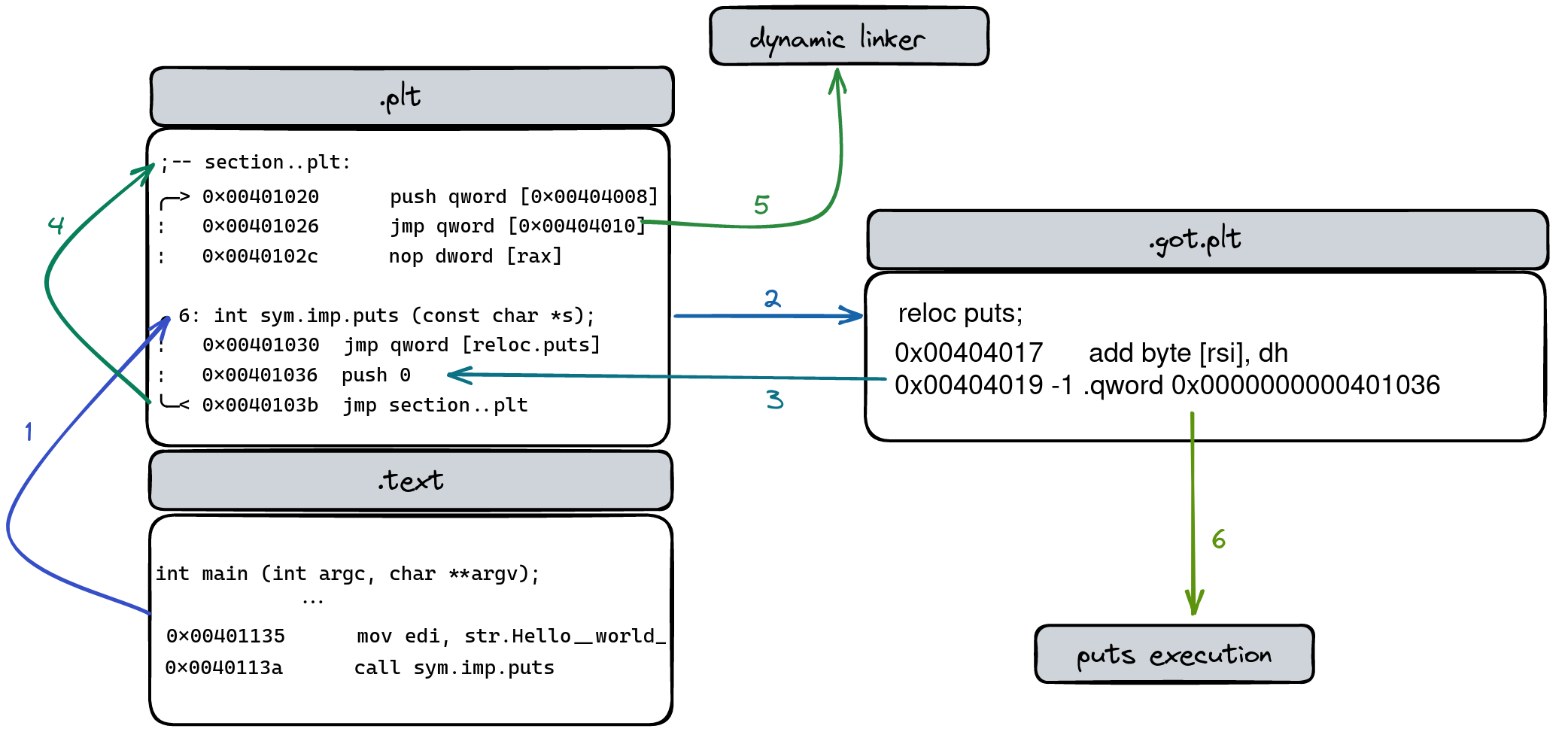
This mechanism enables lazy binding. The first time you call printf, the .plt entry sees that the address in the .got is not yet resolved. It then calls the dynamic linker, which finds the real address of printf in libc.so, updates the .got table with this real address, and then jumps to it. On all subsequent calls to printf, the .plt finds the real address in the .got and jumps there directly, skipping the dynamic linker.
Exploring ELF Binary Dynamics: Relocations and Sections in Depth
The article 'Exploring ELF Binary Dynamics' by kayssel.com has one of the clearest explanations of this PLT/GOT mechanism.
Read the section titled 'Navigating the World of Lazy Binding, PLT, and GOT in ELF Binaries'. Focus on the roles of the PLT and GOT and the step-by-step 'Lazy Binding Ballet' description.
This diagram from the article beautifully illustrates the lazy binding process.
Conclusion
You now have a map of the memory landscape inside an ELF executable. Understanding where your code and data live is not just academic; it's a practical skill essential for optimizing performance, minimizing memory footprint, and debugging low-level issues in embedded systems.
Key Takeaways:
- ELF files have a linking view (sections) and an execution view (segments).
.textholds your executable code and lives in Flash..rodataholds your constants and string literals, also in Flash..dataholds initialized global/static variables. It consumes RAM for the variable and Flash for its initial value..bssholds uninitialized global/static variables. It consumes only RAM, saving Flash space..pltand.gotwork together to enable efficient dynamic linking with lazy binding, a common feature in OS-based embedded systems.
Preview of the Next Lesson:
We've mentioned "startup code" several times today—the code that runs before main() to prepare the .data and .bss sections. In our next lesson, we will investigate this startup sequence in detail, answering the classic interview question: "What happens before main()?" We'll trace the execution flow from the moment the processor resets, through the vector table, and into the C runtime environment.