Hello! Welcome to the first lesson in our module on Thin Lenses.
In our previous module, we concluded our study of refraction through prisms by focusing on solving a wide range of NEET-style problems. You've become proficient at analyzing how light bends when passing through plane surfaces. Now, we shift our focus to refraction through curved surfaces, which is the principle behind lenses.
Today's lesson is designed to build a strong visual foundation, which you've mentioned is your preferred starting point. We will focus entirely on the "how" and "why" of image formation using diagrams. The goal is to construct ray diagrams for convex and concave lenses to determine image characteristics. By the end of this lesson, you'll be able to predict the position, nature (real/virtual), orientation (erect/inverted), and size of an image just by drawing a few simple lines.
Let's begin with the workhorse of optics: the convex lens.
1. Image Formation by a Convex (Converging) Lens
A convex lens is thicker in the middle and thinner at the edges. It's also called a converging lens because it bends parallel light rays so they meet, or converge, at a single point. Before we can draw any diagrams, we need to know the fundamental rules that govern how light rays travel through a convex lens.
To learn these rules and see how they are applied, we'll watch a video that explains them clearly.
This first part of the video from Manocha Academy will introduce you to the convex lens and the three essential rules for ray tracing. Having a notebook and pen to draw along is highly recommended.
Watch the section from 01:03 to 03:46. Pay close attention to the setup of the principal axis (with F1, 2F1 on the left and F2, 2F2 on the right) and the three specific rules for drawing rays.
The Three Rules for a Convex Lens
To summarize the video, here are the three indispensable rules. To locate an image, you only need to draw any two of these rays from the top of the object; their intersection point will be the top of the image.
- Ray parallel to the principal axis: After refraction, it passes through the principal focus on the other side of the lens ().
- Ray passing through the optical center (O): It emerges without any deviation.
- Ray passing through the principal focus on the first side (): After refraction, it emerges parallel to the principal axis. (Note that this is the reverse of Rule 1).

Now that we have the rules, let's see them in action. The position of the object dramatically changes the image that is formed.
Let's continue with the same video. This next segment demonstrates how to apply the rules to construct ray diagrams for an object placed at various positions in front of a convex lens.
Watch from 03:46 to 11:45. Observe how the image's position, size, and nature (real/virtual) change as the object moves closer to the lens, from beyond 2F1 to between O and F1.
Summary of Cases for a Convex Lens
The video provided a dynamic look at how the image changes. For revision and quick reference, a summary table is incredibly useful. The webpage below presents all the cases we just saw with clear, static diagrams and a final summary table that is perfect for NEET preparation.
This resource from Teachoo provides a case-by-case breakdown of image formation by a convex lens. It's a great static reference to solidify what you saw in the video.
Review the ray diagrams for each case, from 'Object is Placed at infinity' to 'Object is between O and F'. Then, carefully study the summary table at the end. This table is a high-yield resource for memorizing the outcomes.
From this, we can see a clear pattern:
- As the object moves from infinity towards the lens, its real, inverted image moves from the focus () away from the lens, getting larger.
- At the special point 2F1, the object and image are of the same size, located at 2F2.
- When the object is placed inside the focal length (between O and F1), the behavior changes completely. The lens acts as a magnifier, producing a virtual, erect, and enlarged image on the same side as the object.
Test your understanding!
Without drawing, predict the characteristics of the image formed by a convex lens when an object is placed at 1.5 times the focal length. Where would the image be formed relative to 2F2?
Show answer
Placing an object at 1.5 times the focal length means it is between F1 and 2F1. Based on the pattern we've learned:
- Nature: The image will be real and inverted.
- Size: It will be enlarged (magnified).
- Position: Since the object is between F1 and 2F1, the image will be formed beyond 2F2.
2. Image Formation by a Concave (Diverging) Lens
Now, let's turn to the other type of spherical lens. A concave lens is thinner in the middle and thicker at the edges. It is a diverging lens because it spreads out parallel light rays that pass through it.
Just like with the convex lens, we have three rules to guide our drawings.
This part of the Manocha Academy video explains the setup and the three fundamental rules for drawing rays through a concave lens.
Watch from 11:45 to 14:09. Note the key difference: for a diverging lens, the rays often appear to come from a focal point.
The Three Rules for a Concave Lens
The rules are similar to the convex lens but with a "diverging" twist. The refracted rays themselves don't meet; instead, we trace them backward to find a virtual focal point.
- Ray parallel to the principal axis: After refraction, it appears to diverge from the principal focus on the same side of the lens ().
- Ray passing through the optical center (O): It emerges without any deviation.
- Ray directed towards the principal focus on the other side (): After refraction, it emerges parallel to the principal axis.
Now let's apply these rules. You'll find that the situation for a concave lens is much simpler than for a convex lens.
Let's see how to construct a ray diagram for a concave lens. As you'll see, the outcome is much more consistent regardless of the object's position.
Watch from 14:09 to 16:37. Observe the characteristics of the image formed. Notice that the refracted rays are diverging and must be extended backward to locate the image.
Summary of Cases for a Concave Lens
As the video shows, a concave lens is quite predictable. No matter where you place the object (except at infinity), a concave lens always produces an image with the same characteristics.
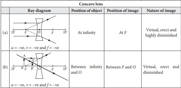
To reinforce this, the following resource provides a clear summary.
Concave Lens: Uses, Formula, Diagram & Image Formation
This Aakash Institute page on concave lenses clearly lays out the image formation rules and characteristics. It's a great text-based summary to complement the video.
Read the section titled 'Image Formation in Concave Lens'. It covers the only two cases you need to know: object at infinity, and object anywhere else on the principal axis.
The key takeaway is simple: A concave lens always forms a virtual, erect, and diminished image, located between the optical center and the focus on the same side as the object.
3. Practice Drawing
Now, let's put your new skills to the test. Grab a pencil and paper. For the following problems, construct the ray diagram and then state the image characteristics.
Problem 1 (Convex Lens): An object is placed at a distance of 40 cm from a convex lens of focal length 20 cm.
- Draw the ray diagram.
- State the position, nature, and size of the image.
Problem 2 (Concave Lens): An object is placed 20 cm in front of a concave lens of focal length 20 cm.
- Draw the ray diagram.
- State the position, nature, and size of the image.
Check your results!
Problem 1 (Convex Lens):
The focal length is 20 cm, so 2F is at 40 cm. The object is placed exactly at 2F1.
- Position: Your ray diagram should show the image forming exactly at 2F2 (40 cm on the other side).
- Nature: The image is real and inverted.
- Size: The image is the same size as the object.
Problem 2 (Concave Lens):
The object is placed at a distance equal to the focal length. However, for a concave lens, the rules are consistent.
- Position: Your ray diagram should show the image forming between the optical center (O) and the focus (F1) on the same side as the object. Specifically, it will be at 10 cm from the lens.
- Nature: The image is virtual and erect.
- Size: The image is diminished (smaller than the object).
Conclusion
Excellent work today! You have successfully built the visual foundation for understanding thin lenses. Mastering ray diagrams is a crucial skill that not only helps in solving problems conceptually but also gives you an intuitive check for answers you'll later calculate mathematically.
Key Takeaways:
- There are three fundamental rules for drawing rays for both convex and concave lenses. You only need two to locate an image.
- Convex lenses are versatile: they can form real, inverted images of varying sizes, or a virtual, erect, and magnified image if the object is within the focal length.
- Concave lenses are consistent: they always form a virtual, erect, and diminished image.
- The terms
real/virtual,inverted/erect, andmagnified/diminishedare the essential characteristics used to describe an image.
Preview of the Next Lesson:
Now that you can visually determine where an image should be and what it should look like, our next step is to do this with mathematical precision. In the next lesson, we will introduce the thin lens formula and the magnification equation. These formulas will allow you to calculate the exact position and size of the image, a skill that is absolutely critical for scoring well on NEET numerical problems.