Hello! Welcome to your next lesson on Zero Voltage Switching.
In our last session, we established a solid understanding of the flyback converter. We saw how it uses a coupled inductor to store energy when the main switch is ON and then transfer that energy to the isolated output when the switch is OFF. This "store-then-transfer" principle is fundamental.
However, our previous model was ideal. In the real world, transformers are not perfect, and a key imperfection called leakage inductance creates significant problems. This lesson tackles that problem head-on. We will explore how a clever circuit, the active clamp, not only solves the issues caused by leakage inductance but also leverages that "problem" energy to achieve Zero Voltage Switching (ZVS).
By the end of this lesson, you will be able to describe how an active clamp circuit recycles leakage inductance energy to achieve ZVS.
The Problem: Leakage Inductance and Voltage Spikes
In an ideal transformer, all the magnetic flux created by the primary winding links with the secondary winding. In reality, some of this flux "leaks" and does not couple to the secondary. This effect is modeled as a small inductor in series with the primary winding, known as leakage inductance ().
While small, this inductor stores energy. When the main flyback switch turns off, the primary current path is broken. The energy stored in the leakage inductance has nowhere to go and induces a very large voltage spike across the switch, which can easily destroy it.
Deciphering Flyback converters active clamps
To understand this problem more clearly, let's watch the beginning of a detailed video by Prof. Sam Ben-Yaakov. He provides an excellent explanation of what leakage inductance is and the dangerous voltage spike it creates.
Watch from 02:50 to 05:05. The video first reviews the basic flyback and then, starting at 02:50, introduces leakage inductance and shows the resulting resonant voltage spike across the switch.
The Brute-Force Solution: The Passive RCD Clamp
For decades, the standard way to protect the switch was to add a passive clamp, typically an RCD (Resistor-Capacitor-Diode) clamp.

This image compares a Passive Clamp Flyback (PCF) on the left with an Active Clamp Flyback (ACF) on the right. Notice the RCD clamp in the PCF circuit, which is designed to dissipate energy.
When the switch turns off, the diode in the RCD clamp turns on, providing a path for the leakage inductance current. The voltage is "clamped" to the voltage on the capacitor, but the energy is ultimately burned off as heat in the resistor.
Increasing Power Density with the Active Clamp Flyback ...
This approach is simple but wasteful. This short tech note from Texas Instruments explains why this is a problem, especially in modern, high-frequency designs.
Read the section titled 'Passive Clamps Dissipate Power'. Focus on how the clamp works and the conclusion that it 'penalizes the overall system efficiency.'
As the note explains, this power loss becomes unacceptable as switching frequencies increase to achieve higher power density. This is the core motivation for finding a more efficient solution.
The Elegant Solution: The Active Clamp
Instead of burning the leakage energy, what if we could capture it and reuse it? This is exactly what the active clamp does. It replaces the dissipative resistor and diode with a second, smaller MOSFET (the "clamp switch" or "auxiliary switch") and a capacitor (the "clamp capacitor").
This simple change transforms the circuit's behavior. Rather than being a problem, the leakage energy becomes a key ingredient for achieving ZVS.
This very brief clip from a Texas Instruments video gives a perfect high-level summary of what the active clamp accomplishes.
Watch from 01:03 to 01:49. The video explains that instead of dissipating the leakage energy, the active clamp stores it and then uses it to achieve ZVS.
The Mechanism: How Recycling Enables ZVS
The process of recycling energy and achieving ZVS is a beautifully orchestrated sequence of events involving both switches and the reactive components. Here is the conceptual flow:
- Store Leakage Energy: When the main switch (Q1) turns off, the leakage inductance current is diverted into the clamp capacitor (Cc), charging it. This clamps the voltage across Q1, protecting it.
- Recycle the Energy: Later in the cycle, the clamp switch (Qc) is turned on. This allows the energy stored in Cc to create a resonant action with the transformer's inductances. This resonance drives the primary transformer current negative.
- Achieve ZVS: Just before Q1 is due to turn back on, the clamp switch Qc is turned off. The negative current stored in the transformer inductance now has to go somewhere. It discharges the parasitic capacitance across Q1 down to 0V. Once at 0V, the current flows through the body diode of Q1.
- Lossless Turn-On: With the voltage across Q1 at zero and its body diode conducting, Q1 can be turned on with virtually zero switching loss.
This process transforms the capacitive turn-on loss, a major source of inefficiency in hard-switched converters, into a recycled energy mechanism.
Exclusive Technology Feature Active Clamp Flyback ...
Let's read a concise description of this process from a How2Power article.
Read the section titled 'How ACF Achieves ZVS'. It clearly states how delaying the clamp switch turn-off develops the negative primary current needed to discharge the switch-node capacitance and achieve ZVS.
A Detailed Walkthrough
Now that you have the high-level concept, we can dive into the detailed waveforms and current paths. The following video is long, but it provides a step-by-step analysis of the entire cycle. We will focus on the most critical part that explains the energy recycling.
Deciphering Flyback converters active clamps
Let's return to Prof. Ben-Yaakov's video for a deep dive into the active clamp's operation. He will walk through the waveforms for each stage of the cycle.
This is a detailed segment. Watch from 16:35 to 33:10. Don't worry about memorizing every detail. Instead, focus on observing the sequence of events: Main Switch Turn-off (starts around 26:30): Watch how the current that was in the main switch now flows into the clamp capacitor. Clamp Switch Turn-on (starts around 28:50): See how the clamp switch turns on while its body diode is already conducting (ZVS for the clamp switch!). Energy Recycling (starts around 30:00): Observe the green waveform (leakage inductor current) and yellow waveform (magnetizing inductor current). Notice how the current reverses and goes negative. This is the energy from the clamp capacitor being put back into the transformer. ZVS Setup (starts around 31:50): The clamp switch turns off, and the negative current discharges the main switch voltage (the blue VDS waveform) down to zero, enabling ZVS.
To help visualize this complex process, the diagram below shows the distinct operating modes of the converter. The cycle we just watched in the video moves through these modes sequentially.
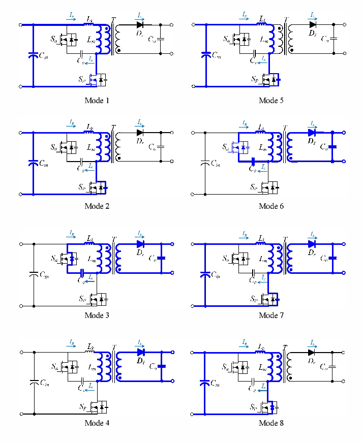
This image shows the eight distinct modes of operation. For example:\n- Mode 2: Main switch turns off, and current flows to charge the clamp capacitor Cc.\n- Modes 4 & 5: The clamp switch Sp is on, and the resonant action between Cc and the transformer inductances (Ll, Lm) causes the primary current to reverse.\n- Mode 7: The clamp switch turns off, and the negative inductor current discharges the main switch's (Sa) output capacitance.\n- Mode 8: The main switch's body diode conducts, setting the stage for ZVS turn-on.
Test your understanding!
In a conventional flyback with a passive RCD clamp, the energy stored in the leakage inductance is dissipated as heat. In an active clamp flyback, where does this energy ultimately go?
Show answer
The energy is not dissipated. It is first stored in the clamp capacitor and then "recycled" back into the transformer's primary winding. This recycled energy is then used to achieve ZVS for the main switch, and any excess is ultimately delivered to the output load, improving overall efficiency.
Conclusion
In this lesson, we transformed a parasitic element—leakage inductance—from a liability into an asset. You've learned how the active clamp circuit elegantly solves the problem of damaging voltage spikes while simultaneously enabling ZVS.
Key Takeaways:
- Leakage inductance is a real-world transformer imperfection that stores energy and causes dangerous voltage spikes when the main switch turns off.
- Passive RCD clamps solve the voltage spike problem but are inefficient because they dissipate the leakage energy as heat.
- An active clamp replaces the dissipative RCD clamp with an auxiliary switch and a capacitor to create a lossless clamping circuit.
- The active clamp recycles the stored leakage energy by using it to generate a negative current in the transformer primary.
- This negative current is the key to achieving ZVS, as it is used to completely discharge the main switch's parasitic capacitance before it turns on.
In our next lesson, we will look closer at the physics of this process. We will examine the resonant transition between the main and clamp switches that facilitates ZVS, focusing on the interplay between the inductances and capacitances that make this efficient switching possible.