Hello! Welcome to the fifth module of our course.
In the previous module, we wrapped up our look at non-isolated converters by examining the significant challenges in making a synchronous boost converter operate with Zero Voltage Switching (ZVS). We saw that unlike the buck converter, the boost topology naturally forces a destructive hard commutation of the body diode, requiring complex solutions like Boundary Conduction Mode (BCM) or auxiliary ZVT circuits to overcome.
Now, we pivot to a new and essential class of converters: isolated converters. These are crucial in power electronics because they provide galvanic isolation, a safety feature that separates the high-voltage input from the user-accessible output. Your work with PCBs, especially those powered from the AC mains, will almost always involve an isolated topology.
Our first stop is the flyback converter, one of the most common and versatile designs for low-to-medium power applications. This lesson is foundational. Before we can apply ZVS to a flyback, we must first understand its unique way of operating. By the end of this lesson, you will be able to explain the operating principles and energy transfer mechanism of a flyback converter.
From Buck-Boost to Flyback
The flyback converter might seem new, but its topology is a direct evolution of the non-isolated buck-boost converter. The key innovation is splitting the single inductor into two galvanically isolated windings.
Designing a flyback DC/DC converter - Fundamentals of flyback converters
To see this evolution visually, let's watch a short clip from a Texas Instruments video on flyback fundamentals. It clearly shows how a buck-boost converter is transformed into a flyback.
Watch from 00:50 to 02:04. Notice how the inductor is first replaced with a coupled inductor (what they call a 'shorted transformer') and then the windings are separated to create the isolated flyback topology.
As the video shows, the core idea is to use a transformer-like component not just to step voltage up or down, but also to create electrical isolation between the input (primary) and output (secondary) sides.
The "Flyback Transformer": A Coupled Inductor
This brings us to the most critical component and the most common point of confusion. The magnetic component in a flyback converter looks like a transformer, is called a transformer, but it does not function like a conventional transformer.
A true transformer is designed to transfer energy instantaneously from primary to secondary with minimal energy storage. A flyback transformer, on the other hand, is fundamentally an energy storage device. It is more accurately described as a coupled inductor.

The main operational difference is this:
- In a true transformer, current flows in the primary and secondary windings at the same time.
- In a flyback transformer (coupled inductor), current flows in the primary OR the secondary, but never at the same time.
This "store-then-transfer" mechanism is the essence of the flyback converter.
How It Works: A Two-Phase Operation
The flyback converter's operating cycle consists of two distinct phases, dictated by the state of the primary-side MOSFET switch.
A concise description of this process comes from the Texas Instruments white paper, "Under the Hood of Flyback SMPS Designs":
Under the Hood of Flyback SMPS Designs
Let's read the brief, clear explanation of the flyback's energy transfer from this TI document.
Please read the single paragraph under the heading 'A. Transfer of Energy'. It perfectly summarizes the two-phase operation.
This two-phase process can be visualized clearly:
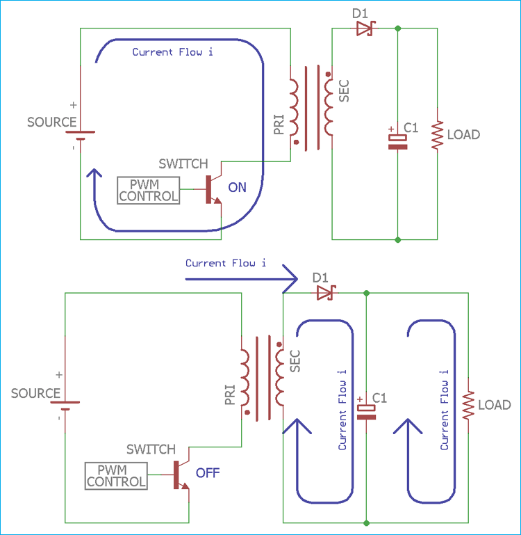
Let's watch a detailed walkthrough of these two phases.
Flyback Converter Basics (for Beginners)
The following video from RGB Engineering gives an excellent conceptual breakdown of the energy storage and energy transfer phases.
Please watch from 12:29 to 17:07. The first part (until 14:19) covers the 'Switch ON' phase, explaining how energy is stored. The second part covers the 'Switch OFF' phase, explaining how that energy is transferred to the output.
To summarize the video's key points:
-
Switch is ON (Energy Storage Phase):
- The input voltage is applied across the primary winding.
- Current ramps up linearly in the primary winding, storing energy in the magnetic field of the coupled inductor's core.
- The polarity of the voltage induced in the secondary winding reverse-biases the output diode. No current flows to the output.
- The output capacitor alone supplies the load current during this phase.
-
Switch is OFF (Energy Transfer Phase):
- The current path on the primary side is abruptly cut off.
- The magnetic field in the core collapses, which induces a voltage of the opposite polarity in both windings.
- This forward-biases the output diode, and the stored energy is now delivered to the secondary side, charging the output capacitor and supplying the load.
- A significant voltage stress, called the reflected output voltage, appears across the primary MOSFET. This is the output voltage, scaled by the turns ratio, plus the input voltage. This is why MOSFETs in flyback converters often need very high voltage ratings (e.g., >600V for offline applications).
Test your understanding!
A colleague is looking at a flyback converter schematic and says, "When the primary switch turns on, power flows through the transformer to the load, just like any other power supply." Is this statement correct? Why or why not?
Show answer
The statement is incorrect. In a flyback converter, when the primary switch is ON, no energy is transferred to the load. Energy is only being stored in the transformer's magnetic field. The load is supplied by the output capacitor during this time. Energy is transferred to the load only when the primary switch turns OFF.
Operating Modes: DCM vs. CCM
Just like the buck and boost converters we've studied, the flyback can operate in different modes depending on the inductor current.
- Discontinuous Conduction Mode (DCM): All the energy stored in the transformer during the ON-time is completely delivered to the output during the OFF-time. The transformer current falls to zero and stays there for a portion of the switching cycle.
- Continuous Conduction Mode (CCM): The load is high enough that the transformer does not have time to fully empty its stored energy before the next switching cycle begins. The transformer current never falls to zero.
Designing a flyback DC/DC converter - Fundamentals of flyback converters
Let's watch another clip from the first TI video, which explains and illustrates the current waveforms for both DCM and CCM.
Watch from 02:04 to 03:56. Pay close attention to the shape of the primary and secondary current waveforms shown for CCM and DCM.
These modes are important for your PCB reviews because the choice between CCM and DCM is a major design trade-off affecting transformer size, peak currents, and overall efficiency. CCM generally has lower peak currents and better efficiency for higher power, while DCM can allow for a smaller transformer and has simpler control characteristics.
A Practical Look at the Components
To tie this all back to your goal of reviewing PCBs, it's helpful to understand the role of each component in the power stage.
Flyback Converter Basics (for Beginners)
The RGB Engineering video provides a great, practical overview of each major component, discussing their purpose and key selection parameters. This is highly relevant for evaluating component choices on a real board.
Please watch the segment from 01:02 to 12:29. It provides a component-by-component breakdown of the flyback power stage: input capacitor, transformer, MOSFET, rectifier diode, and output capacitor.
Conclusion
You now have a solid foundation in the operating principles of the flyback converter. This is a big step, as it's our first look into isolated topologies and its unique energy transfer mechanism is fundamental to many advanced designs.
Key Takeaways:
- A flyback converter is an isolated version of the buck-boost converter.
- Its core component is a coupled inductor (often called a flyback transformer) designed to store magnetic energy.
- Operation is a two-phase process: energy is stored from the input when the switch is ON, and then transferred to the output when the switch is OFF.
- Current flows in the primary winding OR the secondary winding, but never at the same time.
In our next lesson, we will build directly on this knowledge. We will see what happens to the energy stored in the transformer's leakage inductance during the switch turn-off and learn how a clever circuit called an active clamp can recycle this energy to achieve ZVS for the main switch.