Hello! Welcome back to our course on Zero Voltage Switching.
In our last lesson, we established the formulas for energy storage in inductors () and capacitors. We saw that in a switching converter, these components are constantly storing and releasing energy to transfer power from the input to the output.
Today, we'll examine the direct consequence of this dynamic energy transfer: inductor current ripple. This "ripple" is the triangular AC waveform that rides on top of the DC current flowing through the inductor. Understanding, calculating, and controlling this ripple is a fundamental aspect of power converter design and is critical for efficiency and stability.
Your goal is to be able to review and optimize PCBs, and recognizing the implications of inductor current ripple is a key part of that. It influences the choice of the inductor itself, stresses on other components, and the generation of electromagnetic noise.
Let's look at what this ripple looks like in a real circuit.
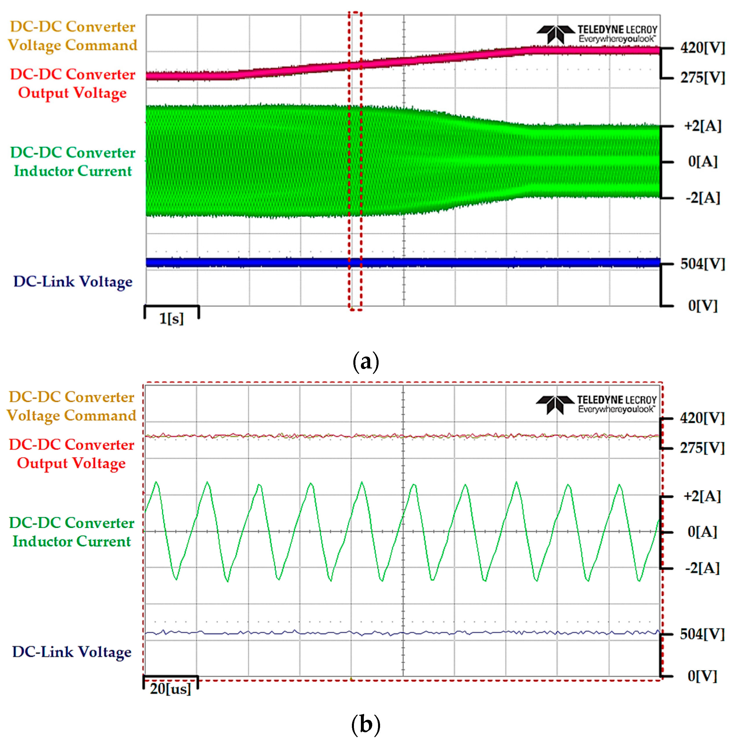
The Origin of Inductor Current Ripple
The ripple's triangular shape is a direct result of the fundamental physics of an inductor, described by the equation . When a constant positive or negative voltage () is applied across an inductor, the current () changes at a constant rate (it ramps up or down linearly).
To see how this works in practice, let's start with a clear, intuitive explanation.
Inductor behavior and Buck Converter Explained
This video from Dr. Sam Ben-Yaakov's channel provides an excellent foundation, showing how applying a constant voltage across an inductor results in a linearly changing current.
Please watch from the beginning to 4:19. Focus on the core concept: a constant voltage produces a constant rate of current change, which appears as a straight line on a current vs. time graph.
Inductor Ripple in a Buck Converter
Now, let's apply this principle to the buck converter, a topology you're already familiar with. In a buck converter, the inductor is switched between two different voltages in each cycle:
- Switch ON: The inductor is connected to the input voltage, . The voltage across the inductor is . Since , this voltage is positive, and the inductor current ramps up, storing energy in its magnetic field.
- Switch OFF: The inductor is connected to ground through a diode (or a synchronous switch). The voltage across it is (ignoring the diode drop for simplicity). This voltage is negative, so the inductor current ramps down, releasing its stored energy to the output capacitor and the load.
This continuous up-and-down ramping creates the characteristic triangular ripple.
Inductor behavior and Buck Converter Explained
The same video now applies this principle to the buck converter. It's a great walkthrough of how the two switching states create the full ripple waveform.
Watch from 9:55 to 14:40. Observe how the inductor voltage is positive during the ON time and negative during the OFF time, and how this directly creates the triangular inductor current waveform.
Calculating Ripple Magnitude ()
We can calculate the peak-to-peak ripple current, , using the fundamental inductor equation. Let's focus on the ON-time, when the current is ramping up:
Since the slope is constant, we can approximate this for the switching interval as:
During the ON time, and . So, the peak-to-peak ripple current is:
Where is the duration the main switch is on, which is the duty cycle times the switching period . Since , we have . This formula is the key to selecting an inductor value.
For a more formal treatment, the textbook slides in "Principles of Steady-State Converter Analysis" (LINK, slide 13) present this same derivation graphically.
The Significance of Ripple: A Core Design Trade-off
The magnitude of the inductor current ripple is not just a byproduct of switching; it's a critical design parameter that you choose. This choice is typically expressed as a current ripple ratio (CRR), which is the peak-to-peak ripple current as a percentage of the average DC output current.
A common rule of thumb is to design for a CRR between 20% and 40%. Why? Because the choice represents a fundamental trade-off between size, cost, and performance.
The following article explains this trade-off perfectly.
Selecting the Right Inductor Current Ripple
So, how much ripple is 'good'? This article from Analog Devices clearly explains why a ripple ratio of around 30% is often a good compromise.
Please read the full, short article. Focus on the sections 'What If the Selected Ripple Current Ratio Is Too High?' and 'What Is the Effect of Selecting a Ripple Current Ratio That Is Too Low?'. This summarizes the core trade-offs you'll see in real-world designs.
To summarize the trade-offs from the article:
- High Ripple ( Small Inductor):
- Pros: Smaller physical size, lower cost.
- Cons: Higher peak currents (stressing switches), higher EMI, requires larger output capacitors to filter, and the circuit enters Discontinuous Conduction Mode (DCM) more easily.
- Low Ripple ( Large Inductor):
- Pros: Lower peak currents, less EMI, smaller output voltage ripple.
- Cons: Larger physical size, higher cost, slower response to load changes.
This image shows what different ripple ratios look like for the same average current.

Continuous vs. Discontinuous Conduction Mode (CCM vs. DCM)
As mentioned in the article, one consequence of high ripple is that the converter can enter Discontinuous Conduction Mode (DCM). This happens when the output current is low enough that the inductor current has time to ramp all the way down to zero during the OFF-cycle.
- CCM (Continuous Conduction Mode): Inductor current always remains above zero. This is the mode we've been analyzing so far.
- DCM (Discontinuous Conduction Mode): Inductor current falls to zero for a portion of the switching cycle.
The transition to DCM changes the converter's transfer function and can affect control loop stability. For now, it's important to know that the choice of inductor and its associated ripple determine the load current at which this transition occurs.
Inductor behavior and Buck Converter Explained
Let's revisit Dr. Ben-Yaakov's video to see a clear visualization of the transition from CCM to DCM.
Watch from 22:27 to 26:15. This segment shows what happens to the inductor current waveform as the load changes and how the converter enters DCM at light loads.
Practical Application: Choosing an Inductor
Now, let's connect all these concepts. In a practical design scenario (or when you're reviewing one), you start with your system requirements (input voltage, output voltage, output current, switching frequency) and a target ripple ratio. You then calculate the inductor value needed to achieve it.
How to Select the Right Inductor for a Buck Converter – Everything You Need to Know in Simple Steps!
This video from Biricha provides a simple, step-by-step guide on how to use the ripple equation to calculate the required inductance.
Watch from 1:32 to 7:20. The video explains the core equation and shows how to rearrange it to solve for the inductance, L, given a desired ripple current, ΔI.
Test your understanding!
Let's apply this to a design scenario. You are reviewing a buck converter design with the following specifications:
- Input Voltage (): 12 V
- Output Voltage (): 3.3 V
- Maximum Output Current (): 2 A
- Switching Frequency (): 500 kHz
The designer has aimed for a current ripple ratio of 30% at maximum load. What value of inductance should they have chosen?
Show answer
Let's break it down into steps:
-
Calculate the Duty Cycle (D):
For a buck converter, . -
Calculate the Target Ripple Current ():
A 30% ripple ratio at 2 A output current means:
. -
Calculate the ON-Time ():
. -
Calculate the Required Inductance (L):
We rearrange the ripple formula to solve for L:Plugging in the values:
So, the required inductance is approximately 7.98 µH. A designer would likely choose the nearest standard value, such as 8.2 µH.
Conclusion
In this lesson, we dissected the concept of inductor current ripple, a crucial parameter in the design and analysis of DC-DC converters.
Key Takeaways:
- Inductor current ripple is the triangular AC current that results from applying alternating positive and negative voltage across the inductor during a switching cycle.
- The magnitude of the ripple is determined by the voltages, switching frequency, and the inductance value: .
- Choosing the inductor value (and thus the ripple magnitude) is a key design trade-off between performance (efficiency, EMI) and physical constraints (size, cost). A common starting point is a ripple ratio of 20-40%.
- The ripple magnitude and average load current determine whether the converter operates in Continuous Conduction Mode (CCM) or Discontinuous Conduction Mode (DCM).
In our next lesson, we will explore the non-ideal aspects of our components. We'll introduce the concepts of parasitic capacitance and inductance, which are "unwanted" electrical properties inherent in every real-world component and PCB trace. Understanding these parasitics is the first step toward understanding switching losses, which is the problem that Zero Voltage Switching aims to solve.