Hello! Welcome back to our course on Zero Voltage Switching.
In our last lesson, we revisited the fundamental voltage-current relationships for capacitors and inductors. We saw that for a capacitor, , and for an inductor, . We also introduced the principles of charge balance and volt-second balance, which are essential for analyzing converters in steady state.
This lesson builds directly on that foundation. Now that we understand how voltage and current behave, we will learn how to calculate the energy stored in these components. Understanding this energy transfer is the core of how a switched-mode power supply (SMPS) works. It's the key to analyzing efficiency, managing component stress, and, ultimately, understanding how ZVS optimizes this energy transfer process.
The Fundamental Formulas for Stored Energy
Capacitors store energy in an electric field, while inductors store it in a magnetic field. Though the mechanisms differ, the formulas for the stored energy are elegantly symmetrical.
Let's begin with a short video that introduces both formulas and provides a helpful conceptual model for what it means for these components to "store" energy.
Energy Stored In Capacitors And Inductors - How, And How Much - Simply Put
This video from the 'Simply Put' channel introduces the formulas for energy storage and provides a great conceptual model for how capacitors store voltage and inductors store current.
Please watch from 0:57 to 2:43. The first part (until 1:50) gives the key formulas. The second part provides a useful way to think about what 'storing energy' means for each component.
As the video explained, the two key formulas we will be working with are:
- For a Capacitor:
- For an Inductor:
Let's look at each one more closely.
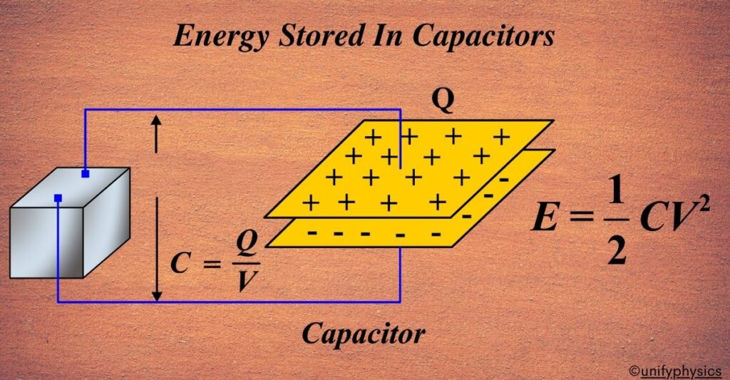
Energy in a Capacitor:
The energy stored in a capacitor is proportional to its capacitance () and the square of the voltage () across it. This relationship is central to the capacitor's role as a filter and local energy source in a power converter. When the output voltage is at its target, the capacitor is "full." When the load suddenly demands more current, the capacitor provides it, its voltage drops slightly, and the stored energy decreases.
The following reading provides a more formal definition in the context of hardware design.
Section 4: Hardware Design Techniques
The 'Hardware Design Techniques' guide from Analog Devices formally defines capacitors as energy storage elements. This section confirms the formula and provides context on their physical construction.
Please read the section titled 'Capacitors' on page 4.2 of the PDF. Focus on the paragraph that begins 'The energy stored in the capacitor...'
Energy in an Inductor:
Similarly, the energy in an inductor is proportional to its inductance () and the square of the current () flowing through it. This makes sense given what we learned last lesson: an inductor resists changes in current. This resistance is due to the energy stored in its magnetic field. To change the current, you must change the amount of stored energy.
Section 4: Hardware Design Techniques
The same Analog Devices guide also discusses inductors as magnetic energy storage elements.
Now, please jump to page 4.24 of the PDF and read the bullet point under the 'Inductor Basic Current/Voltage Relationship' section. It explicitly states the energy formula.
Putting it into Practice: A Calculation Example
Now, let's watch a practical example of how to apply these formulas.
Energy Stored In Capacitors And Inductors - How, And How Much - Simply Put
The same 'Simply Put' video we started with also includes a straightforward calculation. It shows how to calculate the energy in a capacitor and then finds the equivalent current needed for an inductor to store the same amount of energy.
Please watch from 7:23 to 9:40. Follow the calculation for the capacitor and the subsequent calculation for the inductor.
This example highlights an important point: the amount of energy (measured in Joules) might be the same, but it manifests very differently—as voltage in a capacitor and as current in an inductor.
Energy Transfer in a Switching Converter
In a DC-DC converter, we are less concerned with static energy storage and more interested in the continuous transfer of energy from the input to the output. The inductor and capacitor are the vehicles for this transfer.
- The inductor stores energy from the input source during one part of the switching cycle and releases it to the load during the other part.
- The output capacitor acts as a small, local energy reservoir, smoothing out the pulses of energy delivered by the inductor to provide a steady DC voltage to the load.
The following reading explains these roles in the context of the buck and boost converters you are already familiar with.
Section 4: Hardware Design Techniques
To see how this applies to real converters, let's return to the Analog Devices guide. It explains the practical function of these components as energy storage and transfer devices.
First, read the section 'Capacitors for Power Designs: Energy Storage' on page 4.7. Note how it describes the capacitor supplying the load current while the switch is on. Then, read 'Inductor Functions in Switching Converters' on page 4.27. See how it describes the inductor's primary role as an energy storage device in buck and boost converters.
As the text highlights, the change in stored energy during a cycle is what defines the converter's behavior. The current ramping up and down in the inductor represents energy being stored and released. The small voltage drop (droop) on the output capacitor represents the energy it supplied to the load.
Test your understanding!
Let's apply these formulas to a simple circuit. Consider the DC circuit below. Our goal is to find the energy stored in the inductor and the capacitor.

To solve this, we first need to determine the voltage across the capacitor () and the current through the inductor () in DC steady state.
Recall: In DC steady state:
- An inductor behaves like a short circuit (a wire with zero resistance).
- A capacitor behaves like an open circuit (a break in the circuit).
With these rules, can you calculate the energy stored in the inductor and capacitor?
Show answer
-
Analyze the Circuit: In DC steady state, the inductor is a short circuit, and the capacitor is an open circuit. The 4 kΩ resistor is in parallel with the capacitor. Since the capacitor is an open circuit, no DC current flows through that branch, meaning no current flows through the 4 kΩ resistor either. The entire circuit simplifies to the 20 mA current source flowing through the 1 kΩ resistor and the inductor (which acts as a short).
-
Calculate and :
- Inductor Current (): All of the 20 mA from the current source flows through the path of least resistance. Since the inductor is a short, the entire 20 mA flows through it. Therefore, .
- Capacitor Voltage (): The capacitor is in parallel with the 1 kΩ resistor and the inductor. Since the inductor is a short, the voltage across it is 0 V. Because parallel components share the same voltage, the voltage across the capacitor must also be 0 V. Therefore, .
-
Calculate Stored Energy:
- Inductor Energy:
- Capacitor Energy:
- Inductor Energy:
So, in DC steady state, the inductor stores 0.6 mJ of energy, and the capacitor stores 0 J.
Conclusion
In this lesson, we established the fundamental formulas for calculating the energy stored in inductors and capacitors and saw how this energy is dynamically transferred within a switching converter.
Key Takeaways:
- Energy stored in a capacitor is given by .
- Energy stored in an inductor is given by .
- In a switched-mode power supply, these components are not just static storage elements; they are active parts of an energy transfer system that moves power from input to output with each switching cycle.
In our next lesson, we will focus on analyzing inductor current ripple. This ripple is the direct physical manifestation of the inductor charging and discharging energy. Understanding and controlling it is one of the most important aspects of DC-DC converter design.