Hello! Welcome back.
In our last lesson, we focused on the fundamental operations for manipulating single bits: setting, clearing, toggling, and checking. These are the atomic building blocks of low-level programming.
Today, we'll build directly on that foundation to tackle a more complex and common scenario in embedded systems: handling multi-bit fields. Hardware registers often pack multiple pieces of information into a single variable, such as a sensor's resolution, a timer's prescaler value, or specific fields within a CAN message ID. Your goal is to extract and insert these multi-bit fields from/into a variable using bitwise shifts and masks.
This is a skill you've undoubtedly used in your work with AUTOSAR COM stacks and driver development. This lesson will help you formalize the patterns and understand the nuances, ensuring you can articulate them clearly and correctly in an interview.
1. Extracting a Multi-bit Field
Extracting a multi-bit value is a two-step process:
- Isolate: Use a bitwise AND (
&) with a specific mask to zero out all bits except the ones you're interested in. - Align: Right-shift (
>>) the result so the field's least significant bit (LSB) becomes bit 0 of your resulting variable. This "normalizes" the value, making it easy to use.
Let's look at this visually.
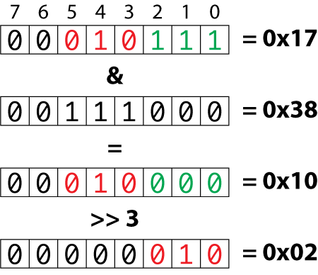
To solidify this concept, let's examine how to implement it in code.
Demystifying bitwise operations, a gentle C tutorial - andreinc
The article "Demystifying bitwise operations" provides a great explanation for creating the necessary masks and performing the extraction.
Please read the subsection titled "Reading multiple bits". Pay close attention to the two different ways the mask is created and how the final result is obtained by combining a mask (&) and a shift (>>). Let i be the starting bit and j be the ending bit of the field.
As the article demonstrates, the core logic is (input & mask) >> i. The clever part is creating the mask. Let's analyze one of the common methods for creating a mask for bits from i to j inclusive:
mask = ((1U << (j - i + 1)) - 1) << i;
Let's break this down:
j - i + 1: This calculates the width of the bit field.1U << width: This creates a value with a single1just to the left of our desired bit field. For a width of 3, this is...0001000.( ... ) - 1: Subtracting 1 from a power of two creates a contiguous block of1s. For a width of 3, we get...0000111.... << i: This shifts the block of1s into the correct starting position,i.
This pattern is extremely powerful and is a great one to have in your toolbox for an interview.
2. Inserting a Multi-bit Field
Inserting a value into a bit field is the reverse process and involves three steps:
- Clear the Field: Create a "hole" in the destination register by clearing the bits where the new value will go. This is done by ANDing with an inverted mask:
reg &= ~mask;. - Position the Value: Take the new value, ensure it's not too large for the field, and left-shift (
<<) it to the correct starting position. - Insert the Value: Use bitwise OR (
|) to place the positioned value into the hole you created in step 1.
The combined operation looks like this:reg = (reg & ~mask) | (value << i);
Let's go back to the same article to see a practical implementation.
Demystifying bitwise operations, a gentle C tutorial - andreinc
The article also provides a function for replacing a bit field, which demonstrates the insertion logic perfectly.
Read the subsection "Replacing multiple bits". Focus on the three main steps in the replace_bits function: creating the clearing mask, clearing the bits in n, and finally shifting and ORing m into place.
The article's replace_bits function demonstrates exactly the clear-and-set pattern we discussed. This is a fundamental technique for register configuration in any low-level driver.
3. A Practical Automotive Example
Let's apply these patterns to a scenario you might encounter. Imagine a 16-bit control register for an ADAS camera sensor, CAM_CONFIG.
- Bits 12-15 (4 bits):
FRAME_RATE_MODE(e.g., 0x3 = 30fps, 0x5 = 60fps) - Bits 4-7 (4 bits):
EXPOSURE_LEVEL(a value from 0-15) - Bit 0:
SENSOR_ENABLE(1 = On, 0 = Off)
Here is how you would write functions to manipulate the EXPOSURE_LEVEL.
#include <stdint.h>
#include <stdio.h>

// Define constants for the EXPOSURE_LEVEL field


#define EXP_LVL_WIDTH 4
#define EXP_LVL_START_BIT 4
#define EXP_LVL_MASK (((1U << EXP_LVL_WIDTH) - 1) << EXP_LVL_START_BIT)
// EXP_LVL_MASK will be 0x00F0

// Extracts the exposure level from the register
uint8_t get_exposure_level(uint16_t reg) {
    // 1. Isolate the field with the mask
    uint16_t isolated = reg & EXP_LVL_MASK;
    // 2. Align it to the LSB
    return (uint8_t)(isolated >> EXP_LVL_START_BIT);
}

// Inserts a new exposure level into the register
uint16_t set_exposure_level(uint16_t reg, uint8_t level) {
    // Ensure the level fits within the 4-bit field
    if (level > 15) {
        level = 15; // Or handle error
    }

    // 1. Clear the field in the register
    reg &= ~EXP_LVL_MASK;

    // 2. Position and insert the new value
    reg |= ((uint16_t)level << EXP_LVL_START_BIT);

    return reg;
}

int main(void) {
    uint16_t cam_config_reg = 0x5001; // Initial value: Frame rate=5, sensor enabled
    printf("Initial register: 0x%04X\n", cam_config_reg);

    uint8_t current_exposure = get_exposure_level(cam_config_reg);
    printf("Current exposure level: %u\n\n", current_exposure); // Expect 0

    printf("Setting exposure level to 10 (0xA)...\n");
    cam_config_reg = set_exposure_level(cam_config_reg, 10);
    printf("Updated register: 0x%04X\n", cam_config_reg); // Expect 0x50A1

    current_exposure = get_exposure_level(cam_config_reg);
    printf("New exposure level: %u\n", current_exposure); // Expect 10

    return 0;
}
Try to trace the logic in main and see how the bitwise operations achieve the desired outcome. Being able to write functions like these is a very common interview task.
4. A Critical Detail: Logical vs. Arithmetic Shifts
So far, we've used unsigned integers (1U) in our masks. This is not just a style choice; it's critical for writing portable and bug-free code. The C standard treats shifts on signed and unsigned integers differently.
- Left Shift (
<<): Behavior is undefined if you shift a negative signed value. It is also undefined if a positive signed value is shifted such that the sign bit is changed. - Right Shift (
>>):- For unsigned types, it is a logical shift. Zeros are always shifted in from the left.
- For signed types, it is implementation-defined. However, nearly all modern compilers perform an arithmetic shift, where the original sign bit is copied into the new bits.
This difference can cause subtle and frustrating bugs.
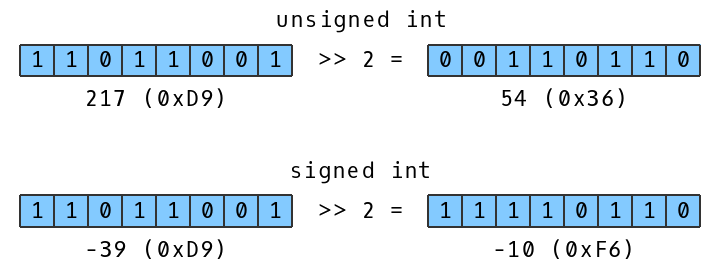
Let's look at why this matters for masking.
Are the shift operators (<<, >>) arithmetic or logical in C?
This Stack Overflow answer provides an excellent, detailed explanation of how shift operators behave in C and the pitfalls to avoid.
Read the 'TL;DR' table for a quick summary. Then, read the 'Shifting' section for the definitions of logical and arithmetic shifts. Next, review the 'Left Shift' and 'Right Shift' sections to understand the C standard's rules. Finally, read the comment starting with 'A classic source of bugs...' near the end, which highlights a very common mistake with ~0 >> 1.
The classic bug mentioned in the resource, ~0 >> 1, is a perfect interview question.
0is a signedintliteral.~0results in-1(all bits1).~0 >> 1on this signed negative value performs an arithmetic right shift. It copies the sign bit, so the result is still-1(all bits1).- The correct way to create a mask with all bits set except the most significant one is
~0U >> 1. By using anunsignedliteral, you guarantee a logical shift, which shifts in a zero.
This is a key piece of knowledge that demonstrates a deep understanding of C's integer promotion rules and operator behaviors.
Conclusion
In this lesson, we expanded from single-bit manipulation to the more versatile task of handling multi-bit fields. This is a daily reality in embedded and automotive programming, and demonstrating fluency here is crucial.
Key Takeaways for Your Interview:
- Extraction Pattern: Isolate then align:
(reg & MASK) >> SHIFT. - Insertion Pattern: Clear then insert:
reg = (reg & ~MASK) | (value << SHIFT). - Mask Creation: Be comfortable creating masks for a given width and start position, for example, using the
(((1U << width) - 1) << start_pos)pattern. - Shift Behavior is Type-Dependent: This is a critical point. Always use
unsignedintegers for bit manipulation to ensure predictable, portable logical shifts and to avoid undefined behavior. Be ready to explain why~0 >> 1is a bug and how~0U >> 1fixes it.
In our next lesson, we will put everything from the last two lessons together. We will practice the ultimate application of these skills: translating a hardware register description from a datasheet into C code for configuration, a task that synthesizes your knowledge of bitmasks, shifts, bit-fields, and the volatile keyword.