Hello! Welcome to the final lesson in our module on low-level data representation and manipulation.
In our last two sessions, we mastered the foundational skills of bitwise operations: manipulating single bits and then progressing to extracting and inserting multi-bit fields. You learned the critical patterns for these tasks and the importance of using unsigned types to ensure predictable, portable code.
Today, we'll synthesize all of these skills to perform a task that is at the very heart of embedded systems and automotive software development: translating a hardware register description from a datasheet into C code for configuration. This is where theory meets practice. Your experience with driver architecture and register-level work in AUTOSAR means you've done this before; this lesson is designed to formalize that process, helping you articulate the "what" and the "why" with precision during an interview.
By the end of this lesson, you will be able to take a description of a peripheral register, like a timer or a communication interface, and write clean, correct, and maintainable C code to configure it.
1. Decoding the "Source of Truth": The Datasheet
Every microcontroller's functionality is documented in its datasheet. This document is the definitive guide to its architecture, peripherals, and, most importantly, its memory-mapped registers. Being able to navigate and interpret a datasheet is a fundamental skill.
A typical register description looks something like this:
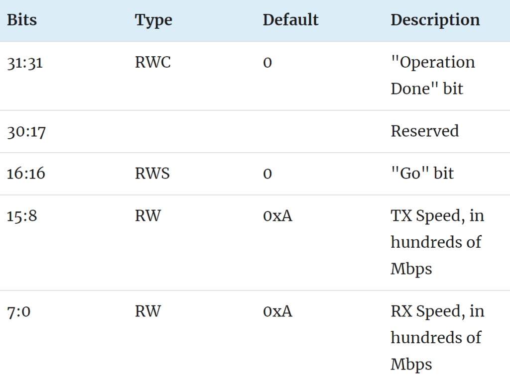
To write code, we need to understand:
- Register Name & Address: Where in memory the register is located.
- Bit Fields: Which bits control which feature.
- Bit Meanings: What values to write to achieve a specific configuration (e.g.,
0x01for "enable,"0x02for "10MHz clock speed"). - Access Type: Whether the bits are Read/Write (R/W), Read-Only (RO), Write-Only (WO), etc.
Microcontroller vendors provide header files (like stm32f4xx.h or <avr/io.h>) that translate these hardware details into C. Let's explore how this mapping is formally defined.
[PDF] Getting Started with Writing C-Code for AVR® MCUs
To understand how datasheet information is structured and systematically translated into C, please read the first two sections of this application note from Microchip. It provides an excellent overview of the conventions used in datasheets and their corresponding C header files.
Please read the following two sections: Section 1: Data Sheet Module Structure and Naming Conventions: Focus on how modules, registers, and bits are described (e.g., Figure 1-3, ADC Register Summary). Section 2: Module Representation in Header Files: Pay close attention to how peripherals are mapped to C structs and how bit masks (_bm), group masks (_gm), and group configurations (_gc) are defined to create a readable API. \nThis will clarify the bridge between the hardware documentation and the code you write.
As you read, notice the key ideas:
- Peripherals are mapped to C
structs, allowing access likeADC0.CTRLA. - Magic numbers are replaced by macros. Instead of writing
(1 << 5), you use a named bit mask likeADC_INITDLY0_bm. - For multi-bit fields, group configuration macros like
ADC_PRESC_DIV4_gcmake the code self-documenting. It's much clearer to writeADC_PRESC_DIV4_gcthan0x01 << 2.
2. A Practical Example: Configuring a USART Peripheral
Now, let's put this into action with a detailed, real-world example. We'll walk through the process of configuring a USART (Universal Synchronous-Asynchronous Receiver-Transmitter) on an STM32 microcontroller to send a character. This is a classic embedded "Hello, World!"
This task requires us to:
- Enable the clocks for the USART peripheral and the GPIO pins it uses.
- Configure the GPIO pins for their alternate function (TX/RX).
- Set the USART baud rate.
- Enable the USART peripheral and its transmitter.
- Wait for the transmit buffer to be empty and write our data.
STM32 #8: Binary, Bitwise Operators, Flags, and Register Control in ...
The following article provides a complete, step-by-step C code example for this entire process. It perfectly demonstrates how to translate register descriptions (which it summarizes from the STM32 reference manual) into a series of bit manipulation operations.
Please read the section titled "USART Communication Example on the STM32F1xx". Follow the logic from enabling clocks to finally writing a byte. As you read the code snippets, try to identify the bit manipulation patterns we've discussed: Setting single or multiple flags with |=. The "clear-then-set" pattern for multi-bit fields. Polling a status bit in a while loop.
Let's break down the most critical part of that example: configuring the GPIO pin PA2 as the transmitter (TX). The reference manual specifies this requires setting a 4-bit field in the GPIOA->CRL register. The target configuration is Alternate function push pull, 50MHz, which corresponds to the bit pattern 1011 (binary) or 0xB (hex).
The code from the article implements this flawlessly using the clear-then-set pattern:
// The 4-bit field for pin 2 starts at bit position 8 (2 * 4).
// 1. Clear the 4-bit field for pin 2
GPIOA->CRL &= ~(0xFu << (2 * 4));

// 2. Set the new configuration value (0xB) in that field
GPIOA->CRL |= (0xBu << (2 * 4));
Let's analyze this:
- The Mask: The mask for the 4-bit field is
0xF << 8. - Clearing:
GPIOA->CRL &= ~(0xF << 8);creates a "hole" in the register at the exact location of the pin 2 configuration bits, leaving all other bits untouched. - Setting:
GPIOA->CRL |= (0xB << 8);shifts the desired configuration0xBinto position and then uses OR to place it into the hole.
This is the direct application of the reg = (reg & ~mask) | (value << shift) pattern from our previous lesson, but now grounded in a real hardware context.
3. Best Practices for Readability and Safety
While the code above is functionally correct, production code, especially in an automotive context compliant with standards like MISRA, emphasizes readability and safety.
Use Defined Macros, Not Magic Numbers
The AVR guide (LINK) you read introduced conventions like _bm (bit mask) and _gc (group configuration). The STM32 headers have similar, though slightly different, conventions. Using these is always preferred.
Instead of this:
// Raw numbers - hard to read and maintain
GPIOA->CRL &= ~(0xFu << 8);
GPIOA->CRL |= (0xBu << 8);
The vendor headers would allow you to write something more like this (conceptual example):
// Using predefined macros - clear and self-documenting


#define GPIO_CRL_CNF2_Pos  (10)
#define GPIO_CRL_CNF2_Msk  (0x3u << GPIO_CRL_CNF2_Pos)
#define GPIO_CRL_MODE2_Pos (8)
#define GPIO_CRL_MODE2_Msk (0x3u << GPIO_CRL_MODE2_Pos)


#define GPIO_AF_PP_50MHZ ((0x2u << 2) | 0x3u) // CNF=10 (AF PP), MODE=11 (50MHz)

// First, clear the entire 4-bit field for Pin 2
GPIOA->CRL &= ~(GPIO_CRL_CNF2_Msk | GPIO_CRL_MODE2_Msk);

// Then, set the new value
GPIOA->CRL |= (GPIO_AF_PP_50MHZ << GPIO_CRL_MODE2_Pos);
This version is verbose but unambiguous. An interviewer will expect you to advocate for this readable and maintainable style.
Avoid C Struct Bit-fields for Hardware Registers
At the end of the STM32 article (LINK), there is a crucial piece of advice:
"Lastly, avoid using pure C bit-fields (structs) for registers. They can break with implementation specific layouts, padding, and non-atomic practices. For hardware registers, masks and shifts are the robust and portable way to do it."
This is a key insight. While it might seem tempting to define a register like this:
// AVOID this for hardware registers
typedef struct {
    unsigned int MODE: 2;
    unsigned int CNF:  2;
    // ... other fields
} GPIO_CRL_PIN2_t;
The C standard leaves the memory layout of bit-fields (e.g., bit ordering, padding) implementation-defined. This means your code might work with one compiler but break with another, or even with different optimization settings. The manual mask-and-shift approach, while more verbose, is fully defined and portable.
Conclusion
You have now completed the journey from individual bit flips to full-fledged hardware peripheral configuration. This process of translating a datasheet's specifications into robust C code is a cornerstone of your field.
Key Takeaways for Your Interview:
- The Process: You can confidently describe the workflow: read the datasheet to identify register addresses and bit field layouts, then use the vendor-provided header files to write configuration code.
- The Core Pattern: For configuring a multi-bit field, articulate the "read-modify-write" sequence, ideally as a single atomic-like operation:
REG = (REG & ~MASK) | (VALUE << SHIFT);. - Code Quality: Emphasize the use of named constants (macros) provided by header files over "magic numbers" to improve readability and maintainability.
- Know the Pitfalls: Be ready to explain why C
structbit-fields are not a robust solution for hardware registers, citing implementation-defined behavior as the primary reason. The mask-and-shift method is the professional, portable standard.
This concludes our module on bit manipulation. In our next lesson, we will pivot from hardware-level details to software architecture. We'll begin exploring Function Pointers and Callback Architectures, a topic that enables the flexible, event-driven designs you see in driver layers and operating systems, including the notification and callback patterns common in AUTOSAR.