Hello! Welcome back to our ray tracing course.
In the last lesson, we made a huge leap in image quality by implementing multi-sample antialiasing. We learned to smooth out jagged edges by casting multiple, randomly jittered rays within each pixel's boundary and averaging the results. This introduced the powerful idea of using randomness to approximate a better result.
Today, we'll leverage a very similar technique to simulate another fundamental property of real-world cameras: depth of field (DoF). Our goal for this lesson is to explain how a camera's aperture and focus distance create depth of field. You'll understand the "why" behind this beautiful effect, which is a cornerstone of photography and cinematography and a key feature in the production renderers you use, like Arnold and Karma.
This lesson will focus on the concepts. In the next one, we'll dive into the C++ implementation.
From Pinhole to Lens: Why Blur Happens
So far, our virtual camera has been a perfect pinhole camera. All rays originate from a single, infinitesimally small point. This has a distinct side effect: everything in the scene is perfectly sharp, from objects right in front of the camera to those infinitely far away. This is called having an infinite depth of field.
Real cameras don't work this way. To capture enough light to form an image in a reasonable time, they need an opening with a finite size, called an aperture. To make the image sharp, a lens is placed in this opening to focus the light onto a sensor.
This system of a lens and a finite aperture can only bring objects at one specific distance into perfect focus. Objects at other distances become progressively blurrier. Let's build an intuition for why this is.
Why aperture affects the Depth of Field
The YouTube channel Tim Klein has an excellent video that uses a simple, physical analogy with strings to explain why a lens creates focus and blur. This provides a great non-mathematical intuition.
Watch from 01:06 to 03:23. The first part (until 01:58) shows how a lens focuses light from a point source onto the film plane. The second part explains what happens when a point source is not at the focal distance, creating what's known as the 'circle of confusion.'
As the video explains, when light from a point on an object doesn't converge perfectly to a single point on the sensor, it forms a small, blurry spot. This spot is called the circle of confusion.

Our perception of "sharpness" is simply when this circle of confusion is so small that we can't distinguish it from a true point.
Controlling the Blur: Aperture and Focus Distance
If a lens and aperture create blur, how do photographers and cinematographers control it? They use two main parameters:
- Aperture Size: This determines the amount of blur for out-of-focus objects.
- Focus Distance: This determines which objects in the scene will be sharp.
The Role of Aperture
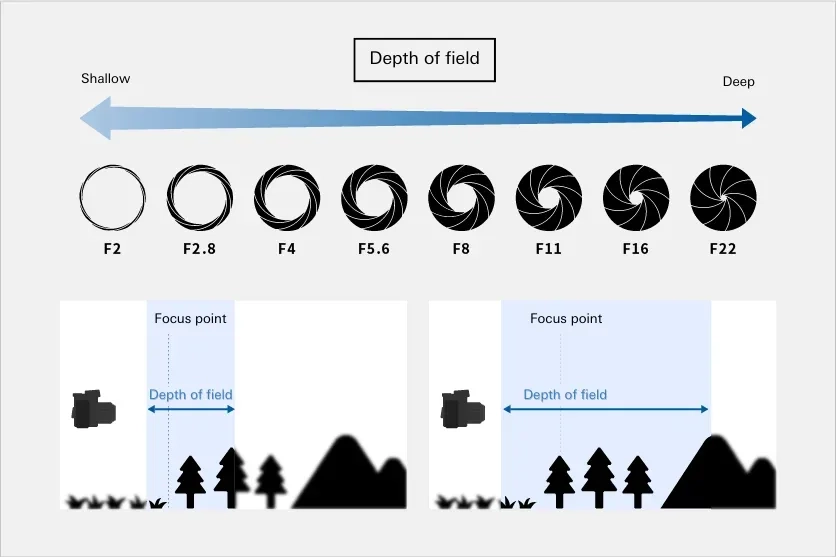
A smaller aperture restricts the light rays to a narrower cone. This has the effect of shrinking the circle of confusion for out-of-focus objects, making them appear sharper and thus increasing the depth of field. Conversely, a wider aperture creates a larger circle of confusion, resulting in more prominent blur and a shallower depth of field.
Why aperture affects the Depth of Field
Let's return to the Tim Klein video to see a physical demonstration of this principle.
Now watch from 03:23 to 04:32. Observe how physically blocking the outer light rays (simulating a smaller aperture) makes the circle of confusion on the film plane smaller.
This relationship is a fundamental creative tool in visual arts. A shallow depth of field (wide aperture) is often used to isolate a subject from its background, while a deep depth of field (small aperture) is used in landscape shots to keep everything from the foreground to the mountains in focus.
The Role of Focus Distance
The focus distance simply sets the distance from the camera to the focal plane. Any object lying on this plane will be perfectly in focus. In a real camera, this is adjusted by moving the lens closer to or further from the sensor. In our ray tracer, it will be a simple distance value that we provide to our camera.
Simulating a Thin Lens in a Ray Tracer
Now, how do we translate this physical reality into our ray tracer? We use a model called the thin lens approximation. Instead of originating all rays from a single point (lookfrom), we'll simulate an aperture by originating rays from random points on a virtual disk centered at that lookfrom point.
This is where the concepts start to click together:
- The radius of this disk is our aperture size. A larger radius means a larger aperture and will produce more blur. A radius of zero gives us our old pinhole camera back.
- To get things in focus, we ensure that all rays, no matter where they start on the disk, converge at the focal plane.
This is the key insight for our simulation:
- Pick a random starting point for the ray on the aperture disk.
- Determine the point on the focal plane that this ray should pass through. This target point is the same for all rays for a given pixel.
- The ray's direction is the vector from the random starting point on the disk to the target point on the focal plane.
Sebastian Lague's 'Coding Adventure: Ray Tracing' video provides an excellent visualization of exactly this simulation technique.
Watch from 34:47 to 35:46. Pay close attention to the animation. It shows multiple rays starting from different points (simulating the aperture) but all converging at the focal plane. This ensures the object on that plane is sharp, while objects before or after it are blurred.
Test your understanding!
Imagine you set an aperture size greater than zero but a focus distance of infinity. What would be the visual result and why?
Show answer
The visual result would be that everything in the scene is equally blurry.
Here's why: With a focus distance of infinity, the focal plane is infinitely far away. This means all the rays originating from the aperture disk for a single pixel will be parallel to each other (since they are all aimed at the same point at infinity). Because the rays are parallel and start from a disk instead of a single point, they will create a blur circle of a constant size on every object they hit, regardless of the object's distance. This is effectively the opposite of a pinhole camera.
Connecting to Production Concepts
The model we've just described is precisely what happens under the hood in production renderers. The parameters we've discussed—aperture_size (or aperture_radius) and focus_distance—are the very same settings you'd find on an Arnold, Karma, or Redshift camera.
For those interested in the more formal optics behind this, the standard textbook Physically Based Rendering provides a thorough treatment. We won't go into the math here, but its diagrams perfectly summarize the algorithm we're building towards.
The book 'Physically Based Rendering' explains the thin lens model used in computer graphics. We won't read the whole text, but a key diagram perfectly illustrates the algorithm we'll eventually implement.
Scroll down to Figure 6.12. You don't need to read all the surrounding text. Just focus on understanding this diagram. Part (a) shows our old pinhole model. Part (b) shows the thin lens model: a ray starts from a sampled point on the lens and is directed through the point where the central ray intersects the plane of focus. This is the algorithm in a picture.
This "thin lens" model is a powerful and efficient approximation that gives us the beautiful and physically plausible depth of field effect that is essential for photorealistic rendering.
Conclusion
You now have the conceptual framework to understand one of the most important artistic effects in computer graphics.
Key Takeaways:
- Depth of field is a natural consequence of using a camera with a finite-sized aperture and a lens, rather than a perfect pinhole.
- Objects that are not on the focal plane are rendered as a blurry circle of confusion on the sensor.
- The aperture size controls the amount of blur. A wider aperture creates a shallower depth of field (more blur).
- The focus distance controls the location of the sharp plane in the scene.
- In our ray tracer, we simulate this by originating rays from a disk (the aperture) and aiming them all through a common point on the focal plane.
Next Steps
With this theory firmly in place, you are ready for the fun part. In the next lesson, we will simulate a thin lens camera by sampling rays originating from a disk representing the aperture. We'll modify our camera class, add the necessary parameters, and bring depth of field to life in our own renderer.