Hello and welcome back!
In the last lesson, you successfully implemented the core logic for a thin lens camera, adding the defocus_angle and focus_dist parameters to your ray tracer. You now have the fundamental tool for creating depth of field.
Today's lesson is about mastering that tool. Our goal is to render scenes with realistic depth of field blur. We won't be writing much new code; instead, we'll focus on understanding how to use the parameters you've already implemented to control the final image, much like a photographer or a VFX artist would. We will explore the visual characteristics of the blur, connect them to the underlying physics, and see how you can use depth of field for artistic effect.
1. A Quick Recap: The Controls of Focus
As a brief reminder from our last session, your camera now has two primary controls for depth of field, based on the implementation in Ray Tracing in One Weekend:
focus_dist: This sets the distance from the camera to the plane where everything is perfectly sharp. In yourmain()function, a good starting point is to set this to the distance betweenlookfromandlookat.defocus_angle: This controls the size of your virtual lens aperture. A value of0gives you a pinhole camera with no blur. As you increase the angle, the aperture gets larger, resulting in a "shallower" depth of field and more pronounced blur for out-of-focus objects.
The interplay between these two parameters is what gives you artistic control.
2. Visualizing the Effect of Camera Parameters
Watching how these parameters affect a render in real-time is the best way to build an intuition for them. Sebastian Lague's video provides an excellent demonstration of this.
Let's watch a segment from 'Coding Adventure: Ray Tracing' that shows the process of adjusting defocus strength and focus distance to achieve different effects.
Please watch from 00:36:10 to 00:37:18. Pay close attention to how changing the 'defocus strength' (equivalent to our defocus_angle) makes the scene blurrier, and how adjusting the 'focus distance' shifts the plane of sharpness from the background to the foreground.
As you saw, a small defocus strength creates a subtle effect, while a large one creates a dramatic, blurry look. The technique shown at the end, where the focus plane is animated from the background to the foreground, is a classic cinematic technique known as a focus pull. This is a powerful storytelling device used to direct the viewer's attention, and you now have the ability to implement it in your own ray tracer.
3. Understanding the "Circle of Confusion"
So, what is actually happening when an object goes out of focus? In an ideal pinhole camera, a single point in the scene maps to a single point on the image. In our thin lens model, a point on the focal plane still maps to a single point on the image.
However, a point not on the focal plane is imaged as a small, blurry disk. This disk is called the circle of confusion. The blur you see in your renders is the result of all these overlapping disks from every out-of-focus point in the scene.

The size of this circle is determined by the aperture size and how far the object is from the focal plane. For a more formal understanding, the Physically Based Rendering book provides an excellent explanation.
Let's dive a little deeper into the optics with a selection from the 'Physically Based Rendering' book. This will formalize the concept of the circle of confusion.
Please read the text in section 6.2.3, starting from 'A point that doesn’t lie on the plane of focus...' down to '...for objects behind it.' Also, pay close attention to the diagrams, especially Figure 6.8 (showing increased blur with a larger aperture) and Figure 6.11 (graphing the size of the circle of confusion).
There are two key insights from that reading:
- The size of the circle of confusion—and thus the amount of blur—is directly proportional to the lens aperture size (
lensRadiusin their code,defocus_anglein ours). This confirms what we've observed. - As shown in Figure 6.11, the blur is asymmetric. Objects in front of the focal plane blur more rapidly than objects behind it. This is a subtle but important characteristic of real-world lens physics that our model now simulates.
4. An Exercise in Artistic Control
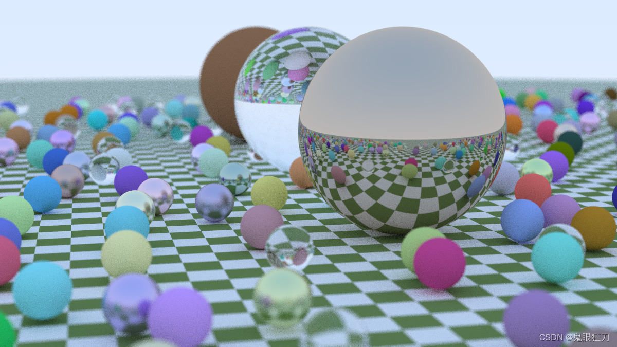
Now it's time to apply this knowledge. Your task is to take the scene you built in the previous lessons and render it three times to demonstrate your control over depth of field. You'll modify the camera settings in your main() function for each render.
Assume your scene has objects in both the foreground and background. You can use the final scene from Ray Tracing in One Weekend as a reference.
Your Renders:
- Deep Focus: Set
defocus_angleto a very small value (e.g.,0.1). Thefocus_distcan be set to the main subject. The goal is to have most of the scene appear sharp, similar to a landscape photograph. - Shallow Focus (Foreground): Set
defocus_angleto a large value (e.g.,10.0). Setfocus_distto the distance of a nearby object, making it sharp while the background becomes very blurry. You can calculate this distance as(lookfrom - foreground_object_position).length(). - Shallow Focus (Background): Keep the same large
defocus_angle(e.g.,10.0). Now, setfocus_distto the distance of a faraway object. The foreground should now be blurry, and the background sharp.
This exercise will give you a tangible feel for how these parameters translate into visual results.
Test your understanding!
You are trying to render a scene with a very shallow depth of field (defocus_angle = 15.0). You notice that the out-of-focus areas (the "bokeh") look circular. You want to make them look more hexagonal, like the aperture of some real camera lenses.
Based on your implementation, where in the code would you need to make a change to achieve this, and what would be the general idea of that change?
Show answer
The change would need to be in the function that generates a random point on the aperture disk, which is random_in_unit_disk() from the previous lesson.
Currently, it samples points uniformly within a unit disk (a circle). To create a hexagonal bokeh effect, you would need to change this function to sample points uniformly within a unit hexagon. This shows that the shape of the blur is a direct projection of the shape of the virtual aperture. This kind of customization is common in advanced production renderers.
Conclusion
You have now fully implemented and explored a key feature of photorealistic rendering. You've not only written the code but also developed an intuition for how to control it to achieve specific artistic goals. This bridge between technical implementation and artistic control is fundamental to high-end computer graphics and is directly applicable to the work done with production renderers like Arnold or Karma.
Key Takeaways:
- Realistic depth of field is controlled by two main parameters:
focus_dist(where the image is sharp) anddefocus_angle(how much blur there is). - The blur itself is formed by overlapping "circles of confusion," which are the projections of out-of-focus points. The shape of this blur mirrors the shape of the virtual aperture.
- These camera properties are powerful tools for visual storytelling, used to guide the viewer's eye, create separation between subject and background, and establish a sense of scale.
Next Steps
With a robust and feature-rich camera model, we can now turn our attention to the objects in our scene. What happens when a ray hits an object? How does light bounce off different surfaces?
In the next module, Surface Materials and Light Scattering, we will begin to answer these questions. We'll start by designing an abstract material class and implementing our first material type: a diffuse, or "Lambertian," surface. This will lead us to implementing recursive ray tracing to simulate light bouncing multiple times around the scene, which is the first step towards true global illumination.