Hello! Welcome back to our ray tracing series.
In the last lesson, we mastered the mathematics of orienting our camera. We learned how to compute the camera's local coordinate system—the u, v, and w basis vectors—from the intuitive lookfrom, lookat, and vup parameters.
Today, we will put that theory into practice. Our goal is to position the camera at an arbitrary point in the scene. We'll modify our camera class to use these parameters, allowing us to generate rays from any viewpoint. This is the crucial step that untethers our camera from the world origin and lets us start framing compelling shots, a core skill in any 3D graphics work, including the VFX pipelines you're familiar with.
Recap: The Camera's Orthonormal Basis
As a brief reminder, we established that a camera's orientation can be described by three mutually perpendicular unit vectors:
w: The vector pointing opposite to the view direction (unit_vector(lookfrom - lookat)).u: The vector pointing to the camera's "right" (unit_vector(cross(vup, w))).v: The vector pointing to the camera's "up" (cross(w, u)).
With this basis, we're ready to position the camera and correctly calculate our rays.
The Camera's Position: The Origin of All Rays
The core idea is simple: the lookfrom point is the camera's position in world space. Therefore, every ray we generate will originate from this point.
The Ray Tracing in One Weekend book makes this explicit in its camera class.
Ray Tracing in One Weekend Series
The section 'Positioning and Orienting the Camera' in Ray Tracing in One Weekend provides the complete C++ implementation for a positionable camera. It's the blueprint for what we're building today.
Please read this section carefully. Pay close attention to the C++ code block for the camera class. Notice how the class now includes lookfrom, lookat, and vup as members, and how the initialize() function uses them. Specifically, find the line where the camera's center is set.
As you saw, the implementation is direct:
center = lookfrom;
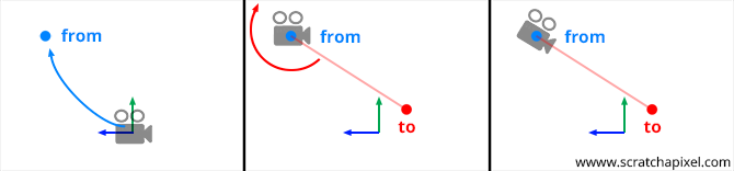
This center point will become the origin for every ray generated by the camera. The following image provides a great visual breakdown of what the "look-at" concept achieves: it first translates the camera to the from point, then rotates it to face the to point.
Updating the Camera's Viewport Geometry
Now that the camera is positioned correctly at center and oriented with its u,v,w basis, we need to update how we calculate the position of the virtual viewport in world space.
In our previous fixed-camera setup, the viewport was on a plane like z = -1. Now, the viewport is positioned relative to the camera's center and oriented by its u,v,w vectors.
Let's re-examine the initialize() function from the Ray Tracing in One Weekend resource you just read. The most important line for calculating the viewport's position is this one:
auto viewport_upper_left = center - (focal_length * w) - viewport_u/2 - viewport_v/2;
Let's break this down:
center: We start at the camera's position.- (focal_length * w): We move from the camera's center along its viewing direction (-w) by thefocal_length. This positions us at the center of the viewport plane.focal_lengthis simply the distance betweenlookfromandlookat.- viewport_u/2 - viewport_v/2: From the center of the viewport, we move half the viewport's width left (along-u) and half the viewport's height up (along+v, but since the book'sviewport_vpoints down, we subtract it). This brings us to the top-left corner of the viewport.
This viewport_upper_left coordinate is now correctly positioned and oriented in world space, no matter where our camera is or where it's looking. From this starting point, we can generate rays for every pixel just as we did before, by stepping along pixel_delta_u and pixel_delta_v.
C++ Implementation Guide
It's time to modify your camera class. Your task is to integrate the logic we've discussed.
Ray tracing from scratch [C++ & SDL2] - Episode 2 - Camera Geometry
The QuantitativeBytes video we looked at last lesson also implements this logic. Watching it will reinforce the C++ structure and how the different member variables come together.
First, review the Camera class header definition from 29:57 to 40:04. Notice the member variables for storing the camera's position, look-at point, and the calculated basis vectors (m_alignment_vector, m_projectionScreenU, m_projectionScreenV). Then, watch the implementation of updateCameraGeometry from 49:00 to 54:03. This is the core logic. Pay close attention to how m_projectionScreenCenter is calculated. It's the same principle as calculating viewport_upper_left in the textbook, but he finds the center of the viewport first.
Based on the resources, update your camera.h and camera.cc files:
- Add member variables for
lookfrom,lookat, andvup. - Create an
initialize()orupdate()method (or do this in the constructor) that:- Sets the camera's origin/center from
lookfrom. - Computes the
u,v,wbasis vectors. - Calculates the world-space location of the top-left pixel (
pixel00_locin the book's terms).
- Sets the camera's origin/center from
- Ensure your
get_ray()method uses the new camera origin and the calculatedpixel00_locto generate rays.
Verifying Your Implementation
How do you know it's working? Change the camera's position and see if the render changes as you'd expect. The Ray Tracing in One Weekend text provides a great example in main.cc.
Ray Tracing in One Weekend Series
The final part of the chapter shows how to use the new camera parameters in main() to generate a new view of the scene.
Review the code snippet for main(). See how new values for cam.lookfrom, cam.lookat, and cam.vup are set before calling cam.render().
Try rendering your scene with the camera at the origin looking down the -Z axis, and then render it again with the new camera position from the book: lookfrom = point3(-2,2,1). You should get a different image that reflects the new point of view.
Test your understanding!
Imagine your scene has a single sphere at the origin (0,0,0). You set your camera with lookat = point3(0,0,0) and vup = vec3(0,1,0).
If you change lookfrom from point3(0,0,5) to point3(0,0,10), how will the rendered image of the sphere change?
Show answer
The sphere will appear smaller. By moving the camera further away from the object (lookat point) along the same line of sight, you are effectively "zooming out". The sphere will still be in the center of the image, but it will cover fewer pixels.
An Alternate View: The Camera-to-World Matrix
In production graphics pipelines, this entire process is often encapsulated in a single 4x4 matrix known as the camera-to-world transformation matrix. Your experience in VFX and with tools like Houdini means you're already familiar with the power of transformation matrices.
The u, v, w vectors and the lookfrom (origin) point form the columns of this matrix. A ray can be defined in "camera space" (origin at (0,0,0), looking down the -Z axis) and then multiplied by this matrix to transform it into the correct position and orientation in world space.
Generating Camera Rays with Ray-Tracing
For a deeper understanding that connects to production systems, the Scratchapixel article on generating camera rays explains this matrix-based approach.
Read the sections 'Finally, we want to be able to render...' and the 'Source Code' snippet that follows. This explains how a cameraToWorld matrix is used to transform the ray's origin and direction from camera space into world space. You don't need to implement this matrix math now, but understanding the concept will be valuable.
This matrix perspective is just another way of thinking about the same problem. The vector-based approach from Ray Tracing in One Weekend is often more intuitive for a first implementation, but both achieve the same result.
Conclusion
Congratulations! You have now implemented one of the most fundamental components of a 3D renderer. Your camera is no longer fixed in space; you can position it anywhere and point it at anything.
Key Takeaways:
- The camera's position in the scene is defined by the
lookfrompoint, which becomes the origin for all generated rays. - The
u, v, wbasis vectors, derived fromlookfrom,lookat, andvup, are used to orient the viewport in world space. - Calculating the viewport's corner location involves starting at the camera's
center(lookfrom), moving along the view direction (-w) to the focal plane, and then shifting to the corner using theuandvvectors. - This entire transformation can also be represented by a single
camera-to-worldmatrix.
Next Steps
Our camera is now positionable and orientable, but its "lens" is fixed. In the next lesson, we will implement an adjustable vertical field of view (FOV). This will give us control over the camera's zoom, completing the set of fundamental camera controls you'd expect in any 3D application.