Hello! Welcome back.
In our last lesson, we gave our camera the freedom to move and look anywhere in our 3D world by implementing the lookfrom, lookat, and vup controls. This was a massive step towards creating dynamic and interesting scenes.
Today, we'll complete our camera model by adding the final essential control: an adjustable "lens". This lesson focuses on implementing an adjustable vertical field of view (FOV). By controlling the FOV, you'll be able to create wide-angle shots that capture a broad panorama or zoom in with a telephoto effect to focus on distant details. This is a fundamental concept in 3D graphics that directly corresponds to choosing a physical camera lens, a process you're likely familiar with from your work in VFX and 3D art.
From Angle to Viewport: The Geometry of FOV
So, what exactly is the Field of View? It's the angle that defines the extent of the observable scene that the camera can see. A wider angle means you see more of the world, while a narrower angle "zooms in". We will use the vertical FOV as our controlling parameter.
The core task is to connect this angle to the physical dimensions of our virtual viewport. Let's visualize the relationship with a simple 2D cross-section.
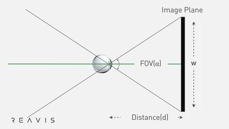
As you can see, the camera's origin, the center of the image plane, and the top edge of the image plane form a right-angled triangle. Basic trigonometry gives us the connection we need.
If:
θ(theta) is our full vertical FOV.- The angle inside our right triangle is
θ / 2. - The "adjacent" side is the distance from the camera to the viewport (our
focal_length). - The "opposite" side is half of the viewport's height (
viewport_height / 2).
Then the relationship is:
Rearranging this gives us the formula to calculate our viewport height from the FOV:
This is the central piece of logic we'll be implementing. The Scratchapixel article provides an excellent, in-depth explanation of this process.
Generating Camera Rays with Ray-Tracing
The article 'Generating Camera Rays with Ray-Tracing' gives a rigorous breakdown of how FOV is incorporated into ray generation. It builds from the basic pixel coordinate transformations we've already seen.
Please read the section that begins with 'Finally, we need to account for the field of view.' It explains the trigonometry with a helpful diagram and derives the scaling factor based on tan(α/2). This will solidify your understanding of the formula we just discussed.
Implementing an Adjustable FOV
Now, let's translate this theory into C++ code. We will follow the approach in Ray Tracing in One Weekend, which integrates seamlessly with our existing camera class.
The plan is to:
- Add a
vfovmember variable to ourcameraclass (e.g.,double vfov = 90;). - In the camera's
initialize()method (or constructor), use thisvfovto compute the viewport's height and width.
Ray Tracing in One Weekend Series
The chapter on the 'Positionable Camera' in Ray Tracing in One Weekend introduces this feature directly. It shows precisely where to add the new vfov member and how to use it to calculate the viewport dimensions.
Read the section 'Positionable Camera', focusing on the subsections 'Camera Viewing Geometry' and the C++ code block that follows. Pay close attention to the highlighted lines where vfov, theta, h, and viewport_height are defined and used. This is your implementation guide.
Based on the reading, here are the key steps to update your camera's initialization logic:
-
Store the FOV: Add a public member variable like
double vfov = 90;to yourcamera.h. We'll use degrees for the user-facing value as it's more intuitive. -
Calculate Viewport Dimensions: Inside your
initialize()function, replace your fixed viewport dimensions with calculations based on the FOV.void initialize() { // ... (previous setup for image_height, center, u, v, w) // Determine viewport dimensions from vfov. auto focal_length = (lookfrom - lookat).length(); auto theta = degrees_to_radians(vfov); auto h = tan(theta / 2); auto viewport_height = 2 * h * focal_length; auto viewport_width = viewport_height * (double(image_width) / image_height); // ... (calculate viewport_u, viewport_v, and pixel00_loc using the new dimensions) // Note: The rest of the logic for calculating viewport_u, viewport_v, // and pixel00_loc remains the same, it just uses the new viewport_width // and viewport_height values. viewport_u = vec3(viewport_width, 0, 0); // This isn't right, we must use the basis vectors! // Corrected calculation from previous lesson: viewport_u = viewport_width * u; viewport_v = viewport_height * -v; // Use -v to go from top-left. // ... (rest of the initialization) }
Notice the focal_length is determined by the distance between the camera and its target. This ensures that as you move the camera further away, the viewport scales appropriately to maintain the same angular field of view, which is the correct behavior.
Test your understanding!
You have your camera set with vfov = 60. If you keep the lookfrom and lookat points the same but change the vfov to 30, will the objects in the center of your rendered image appear larger or smaller? Why?
Show answer
The objects will appear larger. A smaller FOV angle means the viewport height becomes smaller for the same focal length. Since you are mapping the same number of pixels onto a smaller virtual viewport, you are effectively "zooming in," making the objects that fall within that smaller view appear larger.
Verifying the "Zoom"
The best way to see the effect is to render the same scene with different FOV values. You can easily modify your main.cc file to test this.
Ray Tracing in One Weekend Series
The Ray Tracing in One Weekend text demonstrates exactly how to do this.
Look at the short code snippet under 'And we can change field of view:'. It shows setting cam.vfov = 20; before rendering. Try rendering your scene once with a wide FOV (e.g., 90) and once with a narrow FOV (e.g., 20) to see the difference.
After implementing the changes, running your code with different vfov values should produce a clear "zoom" effect, confirming your implementation is working correctly.
Connection to Production Renderers: The Projection Matrix
Your goal is to connect these concepts to production renderers like Arnold or Karma. In those systems, and in real-time graphics APIs like OpenGL or DirectX, the camera's properties (FOV, aspect ratio, near/far clip planes) are typically encoded into a 4x4 perspective projection matrix.
While our vector-based approach is more direct for a simple path tracer, understanding the matrix formulation is invaluable. This matrix transforms points from 3D camera space into a canonical "clip space" cube, creating the illusion of perspective.
The Math behind (most) 3D games - Perspective Projection
The video 'The Math behind (most) 3D games - Perspective Projection' does an excellent job deriving this matrix. Watching the final segment will show you how the very same tan(theta/2) logic we just used is a key component in building this matrix.
Watch from 11:29 to 13:15. The narrator simplifies the perspective matrix and then derives its final form using the vertical field of view and aspect ratio. Notice how tan(theta/2) appears in the matrix. This directly links our implementation to the standard matrix-based approach used in the industry.
This connection is important: while the implementation details differ (vector math vs. matrix transformation), the underlying geometric principle of using the FOV to determine the viewing frustum is universal.
Conclusion
Excellent work! Your camera is now fully functional, equipped with controls for position, orientation, and field of view. This gives you complete artistic control to frame any shot you can imagine.
Key Takeaways:
- The vertical field of view (FOV) is an angle that defines the vertical extent of the camera's vision.
- We use the trigonometric relationship
h = tan(theta / 2)to convert the FOV angle into a concreteviewport_height. - The
focal_length(distance to thelookatpoint) scales the viewport to ensure the angular FOV remains constant regardless of camera distance. - Modifying the
vfovmember variable of your camera allows you to create wide-angle or telephoto (zoomed-in) renderings.
Next Steps
Our camera is complete, but our scenes are still quite simple, containing only one or two spheres. To build truly complex and interesting worlds, we need a way to manage a large number of objects of potentially different types (spheres, planes, triangles, etc.).
In the next lesson, we will begin Module 5 by designing an abstract hittable interface. This is a powerful C++ design pattern that will allow us to trace rays against a list of any type of object in a clean, scalable, and efficient way.