Hello! Welcome back to your journey into building a ray tracer.
In our last lesson, we established the geometric foundation for a camera, learning how to map 2D pixel coordinates to a 3D viewport for a fixed camera. This was a crucial first step.
Now, we'll build on that foundation to give our camera freedom of movement and orientation. Today's learning outcome is to compute camera orientation basis vectors (u, v, w) from look-from, look-at, and view-up parameters. This is the core mechanism that allows you to point your camera anywhere in the scene, a fundamental feature you're familiar with from 3D applications like Houdini.
Introduction: Defining a Camera's Point of View
In any 3D environment, a camera's orientation can be fully described by its position and the direction it's pointing. However, there's one more piece of information needed: its "roll" or rotation around the viewing axis. Think of tilting your head sideways while looking forward.
To capture all this information, we use three intuitive parameters:
- Look-from point (
lookfrom): The world-space coordinate where the camera is located. - Look-at point (
lookat): The world-space coordinate of the point the camera is aimed at. - View-up vector (
vup): A vector that defines the general "up" direction in the world (e.g.,(0, 1, 0)). This is used to fix the camera's roll.
From these three inputs, our goal is to construct a complete, local coordinate system for the camera—an orthonormal basis. This basis consists of three mutually perpendicular unit vectors: u, v, and w.
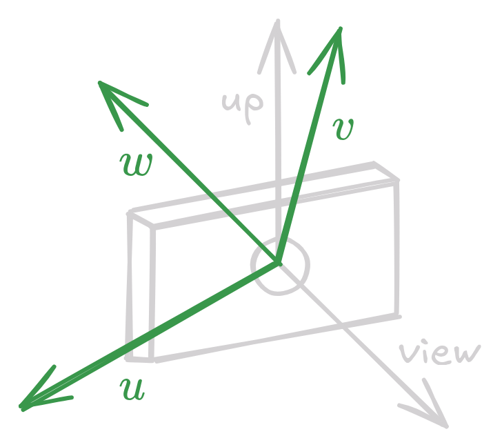
w: A vector pointing opposite to the viewing direction.u: The vector pointing to the camera's "right".v: The vector pointing to the camera's "up".
Your strong background in linear algebra will be a great asset here, as this process is a practical application of vector cross products to construct a coordinate frame.
The Math: Deriving the u, v, w Basis
Let's walk through the derivation step-by-step. We will use a right-handed coordinate system, which is standard.
Step 1: Calculate the View Direction Vector (w)
The camera looks from the lookfrom point towards the lookat point. The vector representing this line of sight is lookfrom - lookat. We normalize this to get a unit vector. By convention in many graphics systems (and in the Ray Tracing in One Weekend book), this basis vector w points out of the back of the camera. Therefore, the camera looks in the -w direction.
Step 2: Calculate the Camera's "Right" Vector (u)
Next, we need the u vector, which points to the camera's right. This vector must be perpendicular to the plane formed by the view direction (w) and the user-provided vup vector. The cross product is the perfect tool for finding such a perpendicular vector.
We take the cross product of vup and w. Using the right-hand rule, this gives us a vector pointing to the right. We normalize it to ensure it's a unit vector. It's important to note that vup might not be perfectly perpendicular to w, but the cross product operation effectively projects it onto the camera's uv plane to find the true perpendicular "up" direction, which we'll calculate next.
Step 3: Calculate the Camera's "Up" Vector (v)
Finally, with w (forward/backward) and u (right/left) defined, we can find the true camera-up vector, v. Since u, v, and w must form an orthonormal basis, v must be perpendicular to both w and u. Another cross product gives us our final basis vector.
Since w and u are already perpendicular unit vectors, the result v will also be a unit vector, so no normalization is needed.
The following resource provides a concise explanation of this exact process.
The chapter on positionable cameras in Ray Tracing in One Weekend succinctly covers the theory behind using lookfrom, lookat, and vup vectors to create an orthonormal basis.
Please read the section titled 'Positionable camera'. Focus on the paragraphs starting from 'To get an arbitrary viewpoint...' to '...our arbitrary view camera faces -w'. This directly explains the derivation of the u, v, and w vectors.
This process of creating an orthonormal basis from a set of vectors is known in linear algebra as the Gram-Schmidt process. The article from LearnOpenGL provides an excellent, complementary explanation of the same concept, referring to the vectors as cameraDirection, cameraRight, and cameraUp. You can explore it for another perspective at https://learnopengl.com/Getting-started/Camera.
Test your understanding!
Suppose you have:
lookfrom= (0, 0, 1)lookat= (0, 0, 0)vup= (0, 1, 0)
What are the resulting w, u, and v vectors?
Show answer
-
Calculate
w:lookfrom - lookat= (0, 0, 1) - (0, 0, 0) = (0, 0, 1).
This is already a unit vector, sow= (0, 0, 1). The camera will look along-w, which is the negative Z direction. -
Calculate
u:vup x w= (0, 1, 0) x (0, 0, 1). The result of this cross product is (1, 0, 0).
This is a unit vector, sou= (1, 0, 0). This is the positive X-axis. -
Calculate
v:w x u= (0, 0, 1) x (1, 0, 0). The result is (0, 1, 0).
So,v= (0, 1, 0). This is the positive Y-axis.
The camera is at (0,0,1) looking at the origin, with its right side along the X-axis and its top along the Y-axis. This is a very standard camera setup.
From Theory to Code
Now, let's put this into practice. We will create a camera class to encapsulate this logic. This class will store the camera's origin, the u, v, w basis, and other parameters. In the previous lesson, we calculated ray directions from a fixed origin and axis-aligned viewport vectors. Now, we will use our new u,v,w basis to orient the viewport correctly in world space.
The key changes to your ray generation logic will be:
- The ray origin is now the
lookfrompoint. - The viewport's horizontal and vertical extents are defined by our new
uandvvectors, scaled by the viewport dimensions. - The location of the lower-left corner of the viewport is calculated relative to the camera's position and its new orientation (
u, v, w).
The following video provides an excellent walkthrough, not only of the geometry but also of a C++ implementation.
Ray tracing from scratch [C++ & SDL2] - Episode 2 - Camera Geometry
This video by QuantitativeBytes visually demonstrates the geometry we've discussed and then dives into a C++ implementation. It's a great way to see how the math translates into a concrete Camera class.
First, watch from 4:20 to 7:18. This is a clear animation of the cross-product logic for finding the U and V vectors. Then, watch from 47:35 to 51:50. This segment focuses on the updateCameraGeometry function in C++. Pay close attention to how it computes the alignmentVector (which corresponds to our w), projectionScreenU (u), and projectionScreenV (v). This is the code you will be implementing.
In the video's implementation, m_alignment_vector is our w. He then calculates u and v and stores them. Note that his full class has additional features like camera length and aspect ratio, which you can integrate into your new camera class.
Your task is to create a camera class that:
- Takes
lookfrom,lookat,vup(and other parameters like FOV and aspect ratio) in its constructor. - Calculates and stores the
u, v, wbasis vectors. - Has a
get_ray(s, t)method that takes normalized screen coordinatessandt(from 0 to 1) and returns a correctly oriented ray for that pixel.
Conclusion
You have now mastered the mathematical foundation for a fully positionable camera. By understanding how to derive an orthonormal basis from intuitive lookfrom, lookat, and vup parameters, you can place and orient your camera anywhere in your 3D world.
Key Takeaways:
- A camera's orientation is defined by a local coordinate system with basis vectors
u(right),v(up), andw(backward). - This basis can be constructed from a
lookfrompoint, alookatpoint, and avupvector using a series of vector subtractions and cross products. - The
wvector isunit_vector(lookfrom - lookat). - The
uvector isunit_vector(cross(vup, w)). - The
vvector iscross(w, u). - Once calculated, these basis vectors are used to orient the viewport in world space, allowing you to generate correctly aimed rays from any position.
Next Steps
In the next lesson, we will finalize the camera class by integrating the field of view and implementing a function to render a scene from multiple viewpoints. This will allow you to fly around your scene and verify that your new, powerful camera controls are working perfectly.