Hello! Welcome to your next lesson.
In our last session, we implemented a crucial debugging technique: visualizing surface normals as colors. This confirmed our ray-sphere intersection logic is working correctly and gave us a robust hit_record structure to carry intersection data, a pattern you'll find is essential as we build more complex scenes.
This lesson marks the beginning of Module 4: Positionable Camera and Scene View. As you requested, we're diving into the camera system early. This will give you the freedom to explore your scenes, a significant step toward creating dynamic and interesting renders.
Today's specific goal is to map pixel coordinates to viewport coordinates using a virtual camera. We'll establish the geometric foundation for our camera—the virtual "film" or sensor—and figure out how to trace a ray through the correct point on this plane for every pixel in our final image.
Introduction: From Pixels to a 3D Viewport
So far, our rays have been somewhat arbitrarily defined. To create a proper camera, we need a precise model. Imagine a simple pinhole camera. Light from the scene passes through a tiny aperture and projects an inverted image onto a film plane behind it.
In ray tracing, we simulate this process in reverse. We cast rays from the pinhole (our camera's position) out into the world, passing through a virtual "screen" or "viewport" that represents our final image. Our main task is to determine the exact 3D direction for the ray that corresponds to each pixel on our 2D screen.
For a great visual introduction to this concept, take a few minutes to watch the following clip.
Ray tracing from scratch [C++ & SDL2] - Episode 2 - Camera Geometry
This video from QuantitativeBytes clearly explains the basic geometry of a ray tracing camera, showing how rays are cast from a pinhole through a virtual screen. This will help you form a strong mental model of what we're about to build.
Watch from 1:52 to 4:55. Focus on the core problem described: given a 2D pixel location, how do we find its corresponding 3D position on the virtual screen to define our ray?
The Geometry of a Simple Viewport
To start, we'll define a simple, fixed camera located at the origin (0, 0, 0) and looking along the negative Z-axis. This is a common convention in graphics. The viewport is a rectangular plane positioned in front of the camera at a certain distance, known as the focal length.
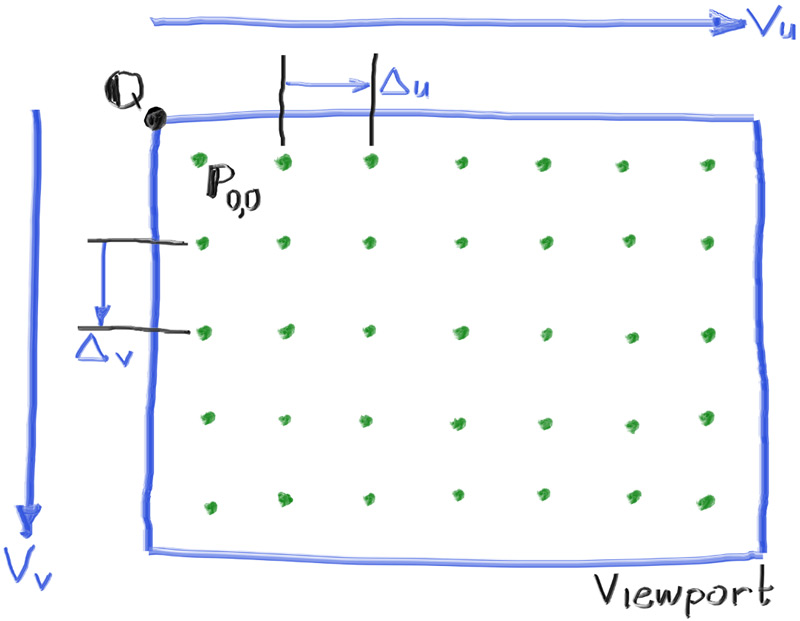
Here are the key parameters we need to define our viewport:
- Image Dimensions: The width and height of our output image in pixels (e.g., 400x225).
- Aspect Ratio: The ratio of the image width to its height. For an image of 1920x1080, the aspect ratio is
1920 / 1080 = 16.0 / 9.0. - Viewport Dimensions: The dimensions of the virtual screen in world-space units. We can set the height arbitrarily (e.g.,
viewport_height = 2.0), and then derive the width from the aspect ratio:viewport_width = viewport_height * aspect_ratio. - Focal Length: The distance from the camera center to the viewport plane. For now, we'll use a
focal_lengthof1.0.
Calculating Pixel Locations in 3D Space
With these parameters, we can compute the 3D world coordinate for the center of any pixel. Since you have a strong background in linear algebra, you'll appreciate this vector-based approach.
-
Establish Viewport Basis Vectors: We need vectors that describe the viewport's orientation and scale. For our simple camera looking down the Z-axis:
- A vector across the horizontal edge of the viewport:
viewport_u = vec3(viewport_width, 0, 0). - A vector down the vertical edge of the viewport:
viewport_v = vec3(0, -viewport_height, 0). (We use a negative Y because our pixel coordinates typically start from the top-left corner, sojincreases downwards).
- A vector across the horizontal edge of the viewport:
-
Calculate Pixel-to-Pixel Spacing: We can find the world-space distance between adjacent pixel centers by dividing the total viewport vectors by the image dimensions:
- Horizontal step per pixel:
pixel_delta_u = viewport_u / image_width. - Vertical step per pixel:
pixel_delta_v = viewport_v / image_height.
- Horizontal step per pixel:
-
Find the First Pixel's Location: The final piece is a starting point. We can calculate the location of the center of the top-left pixel
(0,0).- First, find the location of the viewport's upper-left corner:
viewport_upper_left = camera_center - vec3(0, 0, focal_length) - viewport_u/2 - viewport_v/2. This starts at the camera, moves to the viewport plane, and then shifts to the top-left edge. - Then, find the center of the first pixel by moving half a pixel's width and height from that corner:
pixel00_loc = viewport_upper_left + 0.5 * (pixel_delta_u + pixel_delta_v).
- First, find the location of the viewport's upper-left corner:
-
Putting it all together: To find the center of any pixel
(i, j), we start at the first pixel's center and step across and down:
Once you have the pixel_center in world space, the ray direction is simply the vector from the camera's center to this point: ray_direction = pixel_center - camera_center.
The Ray Tracing in One Weekend book provides an excellent, clear implementation of exactly this logic.
Ray Tracing in One Weekend Series
This chapter from Ray Tracing in One Weekend walks through the C++ implementation for setting up the viewport and generating rays. This is the hands-on part you're looking for.
Read the chapter "Sending Rays Into the Scene." Pay close attention to the code listing highlighted as [main.cc] Creating scene rays. This block contains all the logic described above for calculating viewport_width, pixel_delta_u, pixel_delta_v, pixel00_loc, and finally, the pixel_center inside the loop. This is the code you will be implementing.
By implementing this, you will have created your first simple, but geometrically correct, camera! Your main function will now contain the core logic for a camera, which we will refactor into its own class in a future lesson.
Test your understanding!
Imagine a 100x100 pixel image, a viewport height of 2.0, and a camera at the origin (0,0,0). What would the viewport_u and pixel_delta_u vectors be?
Show answer
- Aspect Ratio:
100 / 100 = 1.0. - Viewport Width:
viewport_height * aspect_ratio = 2.0 * 1.0 = 2.0. viewport_u: This vector spans the horizontal width of the viewport. So,viewport_u = vec3(2.0, 0, 0).pixel_delta_u: This is the horizontal step for each pixel.pixel_delta_u = viewport_u / image_width = vec3(2.0, 0, 0) / 100 = vec3(0.02, 0, 0).
An Alternative View: Coordinate Space Transformations
The vector-based method we just covered is very direct. Another common approach in computer graphics, which you might encounter in shader programming or other rendering contexts, is to think of this as a series of coordinate space transformations.
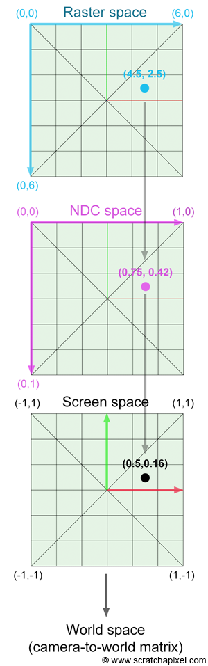
This method involves these steps:
-
Raster Space to NDC Space: Convert pixel coordinates
(i, j)from their integer range to a normalized[0, 1]range. This is called Normalized Device Coordinates (NDC).The
+ 0.5is to find the center of the pixel. -
NDC Space to Screen Space: Remap the
[0, 1]range to[-1, 1], which is more convenient for a centered viewport. The Y-coordinate is also flipped because NDC's origin is usually top-left, while screen space's origin is at the center.The aspect ratio correction ensures the pixels aren't stretched.
-
Screen Space to World Space: With our simple camera, this
(x, y)coordinate now lies on a plane atz = -1(one focal length unit away). The 3D point is(x, y, -1). If the camera were positioned and rotated elsewhere, you would apply a camera-to-world transformation matrix here.
You don't need to implement this second method now, but it's valuable to know it exists as it's a fundamental concept in 3D graphics pipelines. For a deeper dive on this, the "Generating Camera Rays" article on Scratchapixel is an excellent resource.
Conclusion
In this lesson, you've taken the first and most critical step in building a flexible camera system. You now understand the geometry that connects the 2D grid of pixels in your final image to a 3D viewport in your scene.
Key Takeaways:
- A ray tracing camera works by casting rays from an origin point through a virtual viewport positioned in the 3D scene.
- The core task is to map each 2D pixel coordinate
(i, j)to a 3D world-space coordinate on this viewport. - Using vector arithmetic, we can define the viewport's dimensions and orientation, calculate pixel-to-pixel stepping vectors (
pixel_delta_u,pixel_delta_v), and compute the precise center of any given pixel. - The final ray direction is the vector from the camera's center to the calculated pixel center on the viewport.
Next Steps
Now that we have a solid, albeit fixed, camera foundation, the next step is to make it movable. In the next lesson, we will tackle the learning outcome: Compute camera orientation basis vectors (u, v, w) from look-from, look-at, and view-up parameters. This will allow you to place your camera anywhere in the scene and point it at any object, giving you true directorial control.