Welcome to the third lesson in our hardware selection module. So far, we've chosen the ESP32-S3 as the brain of our smart glasses and planned a DIY stereo rig using two camera modules for vision. Now, we need to address a fundamental challenge of any wearable device: power. This lesson will guide you through identifying the power supply requirements for our project and selecting a suitable battery to make the glasses a truly portable, real-time system.
Before we dive in, let's clarify our hardware configuration. The previous lesson mentioned using two ESP32-CAM boards. While that's a valid approach, a more integrated and power-efficient design for our specific goal uses our central ESP32-S3 board to directly manage two separate camera modules (like the OV2640s common on those CAM boards). This consolidates processing onto one chip, simplifying our software and power management. For this lesson, we will base our calculations on this more streamlined architecture: one ESP32-S3 board driving two camera modules.
By the end of this lesson, you will have a clear methodology for estimating power consumption and a strong understanding of the battery and regulation technologies needed to bring our wearable device to life.
1. Estimating Power Requirements: The Power Budget
Before we can pick a battery, we must understand how much power our device will consume. This process, known as creating a "power budget," is a cornerstone of embedded systems engineering. It involves summing the current draw of all active components.
However, our smart glasses won't be running at full tilt every second. They will have different modes of operation: a high-power "active" mode when detecting and processing obstacles, and a low-power "idle" mode for the moments in between. To get a realistic estimate of battery life, we must calculate the average power consumption based on how much time is spent in each mode.
The following article provides an excellent framework for this kind of estimation.
How to Estimate Your Embedded IoT Device Power ...
This blog post by "The Embedded Rustacean" offers a practical, step-by-step guide to calculating power consumption for an embedded device. It clearly breaks down the process from a simple continuous model to a more realistic multi-mode scenario.
Please read through the article, paying close attention to these key parts: The initial sections on system abstraction and identifying components. The explanation of the continuous operation scenario to understand the worst-case consumption. The detailed breakdown of the multi-mode scenario. This is the most important part for our project. Focus on how modes are defined and how the average current is calculated from the time spent in each mode. Finally, review the additional considerations on accuracy and requirements, which provide important context for our own estimates.
2. A Power Budget for the Smart Glasses
Let's apply the multi-mode methodology to our project. We'll define two primary operational states:
- Active Mode: The ESP32-S3 is running at full clock speed, capturing images from both cameras, and performing inference with the neural network. This is the most power-hungry state.
- Idle Mode: The device is "on" but waiting for the next processing interval. The ESP32-S3 can enter a low-power "light sleep" state, waking up periodically. The cameras are powered down or in standby.
To create our budget, we need datasheet values for current draw. These can vary significantly based on the specific ESP32-S3 board, clock speed, and peripherals used. For our estimate, we'll use some typical, conservative values:
- ESP32-S3 (Active, ~240MHz): ~150 mA
- OV2640 Camera (Active): ~40 mA each (so 80 mA for two)
- ESP32-S3 (Light Sleep): ~10-20 mA
- Other components (sensors, quiescent current): ~5 mA
Let's build a table similar to the one in the article you just read. We will assume our system runs inference at 5 frames per second (a 200ms cycle), with the actual processing taking up half of that time.
| Mode | Components Active | Current Draw (Est.) | Time in Mode (per 200ms cycle) | % of Time | Charge (mA*ms) |
|---|---|---|---|---|---|
| Active | ESP32-S3, 2x Cameras, Other | 235 mA | 100 ms | 50% | 23,500 |
| Idle | ESP32-S3 (Sleep), Other | 25 mA | 100 ms | 50% | 2,500 |
| TOTAL | 200 ms | 100% | 26,000 |
Now, we calculate the average current:
This average current draw of 130 mA is our key metric for selecting a battery.
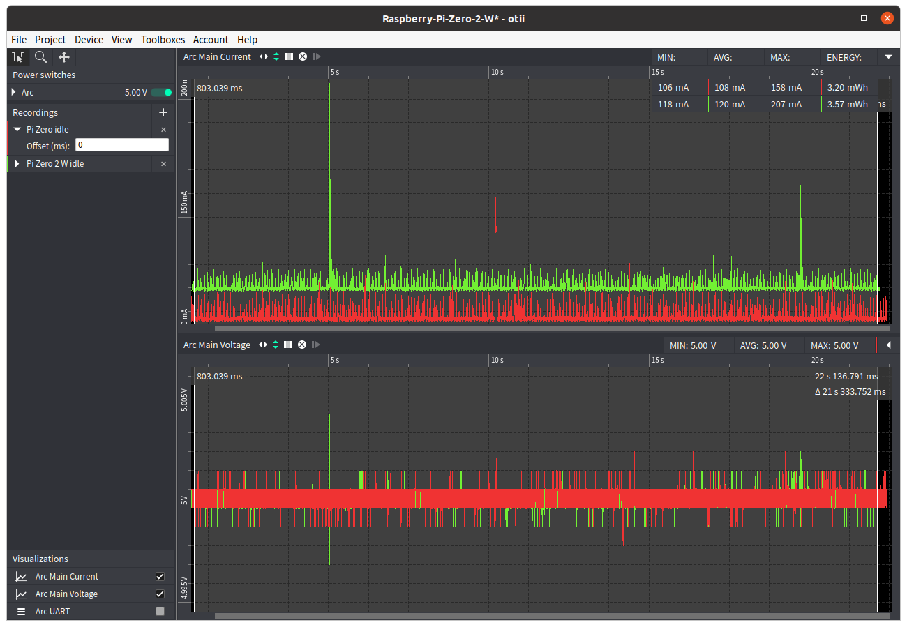
This analysis is a crucial first step. In a real-world project, you would verify these estimates by physically measuring the current draw of your prototype. Specialized tools can produce detailed power profiles, like the one shown below comparing two different Raspberry Pi models.
3. Choosing a Suitable Battery
With an estimated average current of 130 mA, we can now think about battery capacity. Battery capacity is measured in milliampere-hours (mAh). To calculate the required capacity for a target runtime, the formula is:
If we want our glasses to last for at least 2 hours, we would need:
To have some buffer, a battery in the 300-500 mAh range would be a reasonable starting point.
For wearables, the go-to battery chemistry is Lithium-Ion Polymer (LiPo). Let's explore why.
How to Choose the Right Li-Polymer Battery for Wearables
This guide from PKCELL provides a solid overview of LiPo batteries and their application in wearable devices.
Please read the first few sections to understand the fundamentals. Start with the introduction to LiPo batteries and their advantages. Then, review the key factors of capacity, size, shape, and flexibility. Finally, pay close attention to the table in the "Define Your Wearable’s Power Needs" section, specifically the row for AR/VR Glasses. It gives concrete examples relevant to our project.
As the article highlights, LiPo batteries are ideal for our smart glasses due to their:
- High Energy Density: They pack a lot of power into a small, lightweight package.
- Form Factor Flexibility: They can be made in various thin, flat, or even curved shapes, which is critical for designing something that fits on a person's head.

4. Regulation: From Battery Voltage to System Voltage
A LiPo battery's voltage is not constant. A standard single-cell (1S) LiPo provides about 4.2V when fully charged, dropping to around 3.0V when empty. Our ESP32-S3 and its peripherals, however, require a stable 3.3V to operate correctly.
This means we need a voltage regulator—a circuit that converts the fluctuating battery voltage into a steady 3.3V. There are several types, but for a battery-powered device, efficiency is paramount.
The DroneBot Workshop video below gives an excellent overview of the different regulator technologies. We are most interested in the modern, efficient "switching" regulators.
Power For Your Electronics Projects - Voltage Regulators and Converters
This video clearly explains and demonstrates the most common types of voltage regulators and converters used in electronics projects.
First, watch the introduction to buck converters, which are highly efficient at stepping down voltage. Next, watch the segment on boost converters, which do the opposite by stepping up voltage. Finally, and most importantly for our project, watch the explanation of buck-boost converters. Pay close attention to why they are the perfect solution for battery-powered devices where the input voltage can be both higher and lower than the desired output.
As you've just seen, a buck-boost converter is the ideal choice for our smart glasses. It can seamlessly transition from bucking (stepping down) the voltage when the battery is full (e.g., 4.2V -> 3.3V) to boosting (stepping up) the voltage as the battery drains (e.g., 3.2V -> 3.3V). This ensures a stable 3.3V supply throughout the entire discharge cycle, maximizing the usable capacity of our battery.
For context specific to the ESP32, Andreas Spiess provides valuable insights.
#400 The Best Power Source for ESP32/ ESP8266 Projects
In this video, Andreas Spiess, a well-respected voice in the ESP32 community, breaks down power supply strategies for different use cases.
Please watch the section covering Use Case #4, which discusses battery-operated devices that sleep and wake periodically, much like our own. He emphasizes the importance of minimizing every bit of current draw. Then, briefly review the summary flow diagram at the end, which is a great tool for decision-making.
Safety First: The Battery Management System (BMS)
One final, critical component is the Battery Management System (BMS), or Protection Circuit Module (PCM). LiPo batteries can be dangerous if mishandled—over-charged, over-discharged, or short-circuited. The BMS is a small circuit that prevents these conditions. As noted in the PKCELL article, this is an essential part of the power system. Fortunately, most LiPo batteries sold for hobbyist projects come with a basic BMS already integrated. You should never use a "raw" LiPo cell without one.
Conclusion
We've now established a complete strategy for powering our smart glasses. This involved a multi-step engineering process that you can apply to future projects.
Key Takeaways:
- Power Budgeting is Key: A realistic power estimate begins with defining operational modes (e.g., active, idle) and calculating a weighted average current consumption.
- LiPo is the Standard for Wearables: Lithium-Polymer batteries offer the best combination of energy density, low weight, and flexible form factors for our project.
- Efficiency requires Switching Regulators: To maximize runtime from a battery, we must use an efficient DC-DC converter. A buck-boost converter is the ideal topology for providing a stable 3.3V from a 1S LiPo battery.
- Safety is Non-Negotiable: Always use a LiPo battery with an integrated Battery Management System (BMS) to protect against hazardous conditions.
With our compute, vision, and power systems now conceptually defined, we have all the pieces of the puzzle. In the next lesson, we will put it all together, formulating a complete bill of materials for our sub-$100 prototype and justifying the final component choices and trade-offs.