Introduction
Hello again! In our last lesson, we solved a major visual problem by enabling the depth buffer. This ensured that the faces of our 3D cube occlude each other correctly, giving it a true sense of solidity. Your rendering pipeline is now producing visually correct results.
Now that things are correct, let's make them more efficient. Think about your spinning cube: from any angle, you can see at most three of its six faces. The other three faces are on the back, completely hidden from view. Yet, the GPU still processes the vertices and runs the fragment shader for these hidden faces, only for the depth test to discard them at the last moment. This is wasted work.
Today's lesson addresses this inefficiency by implementing a crucial performance optimization. The learning outcome is to: Implement back-face culling as a performance optimization. We'll explore the theory behind how a GPU can identify these "back faces" and then learn the straightforward OpenGL commands to enable this feature, saving valuable processing power.
Why Cull Faces?
The core idea of culling is to discard data as early as possible in the rendering pipeline to avoid unnecessary computation. Back-face culling is a specific technique that discards triangles that are facing away from the camera.
For any closed, solid object (like our cube, a sphere, or a character model), roughly half of its triangles will be facing away from the viewer at any given time. By culling these back faces, we can potentially cut the number of fragments that need to be processed in half, leading to a significant performance boost.

The following reading provides a great introduction to the concept.
Let's start with a clear summary of the problem from the LearnOpenGL guide.
Read the introductory section. It clearly explains the motivation for culling faces we can't see.
The Theory: Winding Order and Normals
So, how do we programmatically determine if a triangle is facing toward or away from the camera? The solution relies on a simple but powerful convention: winding order.
When we define the vertices for a triangle, we list them in a specific sequence. This sequence can be either clockwise (CW) or counter-clockwise (CCW).
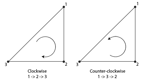
OpenGL uses this winding order to distinguish front faces from back faces. The standard convention is that a triangle whose vertices appear in a counter-clockwise order from the viewer's perspective is considered front-facing.
When you look at a front-facing triangle on a 3D model, you see its vertices in CCW order. But if you could fly around to the back of the model and look at that same triangle, its vertices would now appear to be in a clockwise order from your new point of view. The GPU leverages this change in apparent winding order to identify and cull back faces.
The following resources explain this core concept in more detail. The reading explains how OpenGL uses winding order after vertices have been projected to the screen, while the video explains an alternative (but related) method used in software renderers involving vector math. Understanding both will give you a robust mental model.
First, read this section from LearnOpenGL to understand how winding order is the key to identifying front and back faces in the hardware pipeline.
Read the 'Winding order' section. Pay close attention to how the apparent winding order of a triangle changes depending on the viewer's perspective.
While OpenGL handles this check automatically on the GPU, it's valuable to understand the underlying mathematics, especially as you're building an engine from the ground up. This math is what you would implement in a software renderer.
The process involves two key vector operations you've encountered before: the cross product and the dot product.
- Calculate the Face Normal: We can find a vector that is perpendicular to the triangle's surface (its normal vector) by taking the cross product of two edge vectors of the triangle. The winding order is critical here:
v0 -> v1 -> v2will produce a normal pointing in the opposite direction ofv0 -> v2 -> v1. - Check the Normal's Direction: We then calculate the dot product of this normal vector and a vector pointing from the camera to the triangle.
- If the result is negative, the vectors point in generally opposite directions. This means the normal is pointing towards the camera, so it's a front face.
- If the result is positive, the vectors point in generally the same direction. The normal is pointing away from the camera, so it's a back face and can be culled.
3D Programming Fundamentals [Backface Culling] Tutorial 6
This video from ChiliTomatoNoodle provides an excellent walkthrough of the vector math behind culling. It's based on a left-handed coordinate system (common in DirectX), while OpenGL is right-handed, but the mathematical principles are identical.
Watch the following segments: Dot Product for Culling (05:12 - 07:11): Understand how the dot product determines if a face is pointing toward the camera. Cross Product for Normals (09:33 - 10:48 & 19:21 - 21:01): See how the cross product is used to calculate the face normal from the triangle's vertices. Winding Order (25:58 - 28:00): This part connects everything, showing how the vertex winding order directly impacts the direction of the calculated normal.
Implementing Back-Face Culling in OpenGL
Fortunately, you don't need to implement the cross and dot product logic in your C code. OpenGL and the graphics driver do all of this for you on the GPU. All we need to do is:
- Ensure our vertex data has a consistent winding order.
- Enable the culling feature and tell OpenGL which convention we are using.
1. Update Vertex Data
First, we must ensure the vertices for our cube are defined with a consistent counter-clockwise (CCW) winding order for every face when viewed from the outside. The vertex data we've used so far might not have this.
You can find an updated vertex array for a cube with the correct CCW winding order in the LearnOpenGL article, within the "Face culling" section. Replace your existing cube vertex data with this new data.
To check this yourself, use the right-hand rule for one of the faces. For example, for a triangle with vertices v1, v2, v3 in CCW order: point the fingers of your right hand from v1 to v2, then curl them towards v3. Your thumb will point in the direction of the front-face normal. For an outside face of the cube, your thumb should point outwards.
2. Enable Culling in Code
The OpenGL commands for this are very simple. You only need to set this up once during initialization.
Face culling - LearnOpenGL & Tutorial 8
This final reading from LearnOpenGL and a snippet from a university tutorial show the exact functions you'll use.
Read the section titled 'Face culling' in the LearnOpenGL article. It covers glEnable(GL_CULL_FACE), glCullFace, and glFrontFace.
Based on the reading, add the following lines to your initialization code, right after you enable the depth test:
// In your initialization code, after glEnable(GL_DEPTH_TEST);

// Enable back-face culling
glEnable(GL_CULL_FACE);

// Specify that we want to cull back faces
glCullFace(GL_BACK);

// Specify that our front faces are defined by a counter-clockwise winding order
glFrontFace(GL_CCW);
After updating your vertex data and adding these three lines, run your program. The cube should look identical from the outside. However, if you were to "fly" the camera inside the cube, you would see that the interior is gone—all the back faces have been culled! The GPU is now doing less work to render the same result.
Limitations of Back-Face Culling
Back-face culling is a powerful optimization, but it's not a silver bullet. It's important to know when not to use it.
- Non-closed objects: A flat plane, like a blade of grass or a sheet of paper, needs to be visible from both sides. Enabling back-face culling would make it disappear when viewed from behind.
- Transparent objects: When rendering transparent objects like glass, you often want to see the back faces through the front faces. Culling is typically disabled when rendering transparent objects.
The video below briefly demonstrates scenarios where back-face culling alone isn't sufficient, reinforcing the need for the depth buffer you implemented previously.
3D Programming Fundamentals [Backface Culling] Tutorial 6
To wrap up, this segment from the ChiliTomatoNoodle video discusses the limitations of back-face culling, showing cases like concave shapes where it can't solve all visibility issues on its own.
Watch from 28:52 to 34:35. Notice how back-face culling works for a single convex object but fails for overlapping or concave objects. This highlights why it's an optimization layer on top of depth testing, not a replacement for it.
Conclusion
Great work! You've added another essential optimization to your rendering engine. By understanding and implementing back-face culling, you're now instructing the GPU to be smarter about its workload, avoiding the cost of processing triangles that will never be seen.
Key Takeaways:
- Back-face culling is a performance optimization that discards triangles facing away from the camera.
- The GPU determines front vs. back faces based on the winding order of a triangle's vertices (clockwise vs. counter-clockwise) from the viewer's perspective.
- The standard OpenGL convention is to treat counter-clockwise (CCW) triangles as front-facing.
- Mathematically, culling can be understood by using the cross product to find a face normal and the dot product to check its orientation relative to the camera.
- You enable this in OpenGL with
glEnable(GL_CULL_FACE)after ensuring your model's vertices have a consistent winding order.
Preview of the Next Lesson:
Our cube is now rendered correctly and efficiently, but it's still just a set of solid-colored faces. The next step in bringing our 3D world to life is to apply images to the surfaces of our models. In the first lesson of our next module, "Texturing and Basic Lighting," you will learn how to load image data from a file and prepare it for use in OpenGL as a texture.