Introduction
Welcome back! In our last lesson, we mastered indexed drawing with Element Buffer Objects (EBOs), which allowed us to define complex shapes efficiently by reusing vertices. We've now established a complete pipeline on the C-side of our application to send vertex data to the GPU.
So far, however, the programs that run on the GPU—the shaders—have been a complete black box. We've been using them without understanding what they do or how they work. This lesson changes that.
Our goal is to write a basic vertex shader in GLSL to process vertex positions. We will open up the "black box" and take our first steps into GPU programming. You'll learn what a vertex shader is, its role in the graphics pipeline, and how to write a simple one using the OpenGL Shading Language (GLSL) to control the position of your vertices.
What is a Vertex Shader?
The graphics pipeline is a sequence of stages that transforms your 3D vertex data into the 2D colored pixels you see on screen. The very first programmable stage in this pipeline is the vertex shader. Its fundamental job is to run once for every single vertex you send to the GPU and determine its final position.
To get a high-level overview of shaders and their role, let's start with a short video.
OpenGL Shaders | Game Engine series
Watch this segment from The Cherno's 'OpenGL Shaders' video. It provides an excellent conceptual introduction to shaders, distinguishing between the two most important types: vertex shaders and fragment (or pixel) shaders.
Watch from 06:33 to 12:36. Focus on understanding these key points: Shaders are programs that you write, which run on the GPU. The vertex shader runs per vertex. Its primary job is to calculate the final position of that vertex. The fragment shader runs per pixel. Its job is to calculate the final color of that pixel. We will cover this in the next lesson.
As the video explained, the vertex shader's main output is the final position of a vertex. But what coordinate system is that position in?
The Target: Normalized Device Coordinates (NDC)
OpenGL only renders things that are within a specific, cube-shaped region of space where the x, y, and z coordinates all range from -1.0 to 1.0. This is called Normalized Device Coordinates (NDC). The vertex shader's ultimate goal is to output coordinates that will end up in this space. Anything outside this range is "clipped" and won't be visible.
Hello Triangle - Vertex Input and NDC
The LearnOpenGL article 'Hello Triangle' has a great section that explains NDC and the role of the vertex shader in producing coordinates for this space.
Read the section titled 'Vertex input'. Pay close attention to the diagram and description of Normalized Device Coordinates. This is the coordinate system that the vertex shader's output is transformed into.
The output of the vertex shader is technically in "clip space," which is then converted to NDC by dividing by its w component. For now, you can think of the vertex shader's job as simply outputting the position in this -1.0 to 1.0 cube.
Writing Your First Vertex Shader in GLSL
Now, let's write the code. Shaders are written in a special language called GLSL (OpenGL Shading Language), which has a syntax very similar to C.
Here is the simplest possible vertex shader:
#version 330 core

layout (location = 0) in vec3 aPos;

void main()
{
    gl_Position = vec4(aPos, 1.0);
}
This might look a little strange, so let's break it down line-by-line.
Hello Triangle - Vertex Shader
The 'Vertex shader' section in the LearnOpenGL article provides a perfect, detailed breakdown of the code we just saw.
Read the section titled 'Vertex shader'. It will walk you through each part of the code, from the version declaration to the all-important gl_Position.
Let's recap the most important parts:
-
#version 330 core: Specifies we're using GLSL version 3.30 and the modern "core" profile, which disallows old, deprecated functions. -
layout (location = 0) in vec3 aPos;: This is how we get data into the shader.in: Keyword for an input variable coming from the vertex buffer.vec3: A GLSL data type representing a 3-component vector (x, y, z).aPos: A name we've chosen for our position attribute variable.layout (location = 0): This is the crucial link! It explicitly connects this shader input to attribute location 0 in our C code—the same location we configured withglVertexAttribPointer(0, ...)and enabled withglEnableVertexAttribArray(0).
-
void main() { ... }: The entry point for the shader, just like in C. This code will be executed for every vertex. -
gl_Position = vec4(aPos, 1.0);: This is the shader's output.gl_Position: A special, built-in GLSL variable. Whatevervec4value you assign to it becomes the final clip-space position of the vertex.vec4(aPos, 1.0): We must output a 4-component vector (vec4). We construct it using our 3-component inputaPosfor x, y, and z, and set the fourth component,w, to1.0. Thewcomponent is used for perspective calculations, which we'll cover in detail later. For now, think ofw = 1.0as indicating a point in 3D space.
This simple shader does no processing; it just takes the input position and passes it directly to the output.
The Shader in Action
Visually, you can think of the process like this:
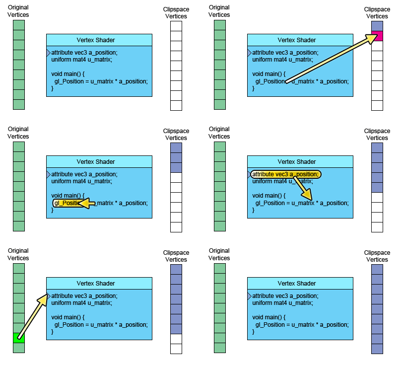
In your C application, you will eventually load this shader code as a simple string. The next lesson will cover compiling this string into a usable GPU program, but seeing how it's stored can be helpful now.
This short clip from another Cherno video shows the GLSL code being written directly inside a C++ string. It helps to visualize how the shader code you just learned lives within your application before it's sent to the GPU for compilation.
Watch from 19:18 to 22:15. You don't need to understand the C++ code around it yet. Just focus on how the GLSL vertex shader code is written as a multi-line string. Notice how it matches the structure we just discussed.
Hands-On Experiment: Modifying gl_Position
The best way to understand what the vertex shader does is to play with it. What happens if we don't just pass the position through, but modify it?
Consider this slightly changed shader:
#version 330 core

layout (location = 0) in vec3 aPos;

void main()
{
    // Move every vertex 0.5 units to the right
    gl_Position = vec4(aPos.x + 0.5f, aPos.y, aPos.z, 1.0);
}
If our input vertices defined a triangle centered at the origin, this shader would take each vertex and add 0.5 to its x-coordinate before outputting the final position. The result? The entire triangle would be rendered shifted to the right.
This simple modification demonstrates the power you now have. You can manipulate every vertex on the GPU to translate, rotate, scale, or deform your geometry in any way you can imagine.
OpenGL Shaders | Game Engine series
To see this principle in action, watch this final clip. The presenter makes a similar change to his vertex shader and shows the immediate result.
Watch from 34:00 to 35:15. This demonstrates how changing the calculation for gl_Position directly affects the rendered geometry on screen.
Conclusion
Congratulations! You've taken your first step into the world of shader programming. While this first vertex shader was simple, it laid the foundation for all the advanced visual effects to come.
Key Takeaways:
- A vertex shader is a program that runs on the GPU for each vertex, with its primary goal being to compute the vertex's final position in clip space.
- Shaders are written in GLSL, a C-like language.
- The
inkeyword declares input attributes, which are linked to your VBO data usinglayout (location = ...). - The special built-in variable
gl_Positionis thevec4output that determines the vertex's final position. - By manipulating the calculation for
gl_Position, you can directly transform your geometry on the GPU.
Preview of the Next Lesson:
A vertex shader is only half of the story. Once OpenGL knows where the vertices of a triangle are, it needs to fill in the pixels inside. This is the job of the fragment shader. In the next lesson, "Write a basic fragment shader in GLSL to output a solid color," you will write your second shader and learn how to control the color of your rendered shapes.