Introduction
Welcome to the next lesson! In our previous session, you successfully loaded image data and transferred it to the GPU by creating and configuring an OpenGL texture object. You now have a 3D model (your cube or a quad) and a texture, both residing in GPU memory, but they exist independently. OpenGL doesn't yet know how to apply the 2D image to the 3D surface.
Today's learning outcome is to define texture coordinates (UVs) as a vertex attribute to map textures onto a mesh. We are going to build the "map" that tells OpenGL precisely which part of the texture should go on which part of your geometry. This involves updating your vertex data, reconfiguring how OpenGL reads that data, and modifying your shaders to make use of this new information.
By the end of this lesson, you will be able to wrap a 2D texture around a 3D object, a fundamental step in making any game visually rich.
What are Texture Coordinates?
A texture is a 2D image, so it has its own 2D coordinate system. In graphics, we call these texture coordinates or, more commonly, UV coordinates. The 'U' axis corresponds to the horizontal direction (like X), and the 'V' axis corresponds to the vertical direction (like Y).
By convention, these coordinates are normalized, meaning they range from 0.0 to 1.0 regardless of the texture's pixel dimensions.
(0, 0)is the bottom-left corner of the texture.(1, 0)is the bottom-right corner.(0, 1)is the top-left corner.(1, 1)is the top-right corner.
To map a texture onto a triangle or any polygon, we assign a specific UV coordinate to each of its vertices. OpenGL then automatically interpolates these coordinates across the surface of the polygon for every pixel, figuring out which part of the texture to sample from.
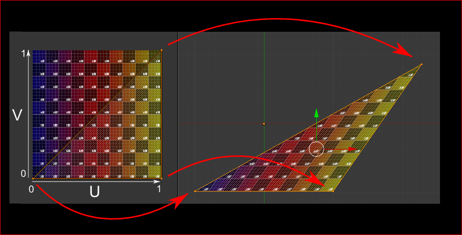
This process of assigning UVs to a 3D model's vertices is called UV unwrapping. Artists typically perform this step in 3D modeling software like Blender or Maya, where they "flatten" the 3D model's surface into a 2D layout, much like creating a sewing pattern from a piece of clothing.
Introduction to Texturing & LearnOpenGL - Textures
To get a solid grasp of the core concepts, please read the introductory sections from Scratchapixel and LearnOpenGL. They provide excellent explanations of what UVs are and why they are needed.
From the Scratchapixel article, read the 'Basic Implementation' section and the following subsection 'How does this work' down to the paragraph that begins 'To summarize...'. This will introduce the concept and the term 'UV unwrapping'.
1. Updating Vertex Data with UVs
To implement this, we must add two floats (for U and V) to each vertex in our data array. Previously, your vertex data might have just included position (x, y, z). Now, it will be structured like this: x, y, z, u, v.
Let's start with a simple rectangle (composed of two triangles) to make the mapping clear. We'll map the entire texture to this rectangle.
float vertices[] = {
    // positions          // texture coords
     0.5f,  0.5f, 0.0f,   1.0f, 1.0f, // top right
     0.5f, -0.5f, 0.0f,   1.0f, 0.0f, // bottom right
    -0.5f, -0.5f, 0.0f,   0.0f, 0.0f, // bottom left
    -0.5f,  0.5f, 0.0f,   0.0f, 1.0f  // top left
};

unsigned int indices[] = {
    0, 1, 3, // first triangle
    1, 2, 3  // second triangle
};
Notice how the texture coordinates (0.0, 0.0) correspond to the bottom-left vertex (-0.5, -0.5), and (1.0, 1.0) corresponds to the top-right vertex (0.5, 0.5), effectively stretching the texture over the quad.
2. Configuring the New Vertex Attribute
Since we've changed the structure of our vertex data, we must tell OpenGL how to interpret the new layout in the Vertex Buffer Object (VBO). This is where the concepts of stride and offset become crucial.
- Stride: The number of bytes between the start of one vertex's data and the start of the next vertex's data. For our new layout, each vertex has 3 floats for position and 2 floats for texture coordinates, for a total of 5 floats. So, the stride is
5 * sizeof(float). - Offset: The number of bytes from the beginning of a vertex's data to the start of a specific attribute.
- The position attribute starts at the beginning, so its offset is
0. - The texture coordinate attribute starts after the 3 position floats, so its offset is
3 * sizeof(float).
- The position attribute starts at the beginning, so its offset is
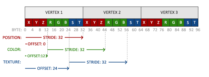
Your glVertexAttribPointer calls will now look like this:
// Position attribute
glVertexAttribPointer(0, 3, GL_FLOAT, GL_FALSE, 5 * sizeof(float), (void*)0);
glEnableVertexAttribArray(0);

// Texture coordinate attribute
glVertexAttribPointer(1, 2, GL_FLOAT, GL_FALSE, 5 * sizeof(float), (void*)(3 * sizeof(float)));
glEnableVertexAttribArray(1);
Note that we use location = 1 for the texture coordinate attribute. If you were also using color, you would use location = 2 and adjust the stride and offsets accordingly.
3. Updating the Shaders
Our shaders need to be updated to accept and use these new texture coordinates.
Vertex Shader
The vertex shader's job is to accept the texture coordinates as an input attribute and pass them through to the fragment shader. OpenGL will automatically interpolate these values for every fragment between the vertices.
#version 330 core
layout (location = 0) in vec3 aPos;
layout (location = 1) in vec2 aTexCoord; // New input attribute

out vec2 TexCoord; // New output to fragment shader

uniform mat4 model;
uniform mat4 view;
uniform mat4 projection;

void main()
{
    gl_Position = projection * view * model * vec4(aPos, 1.0);
    TexCoord = aTexCoord; // Pass texture coordinate to fragment shader
}
Fragment Shader
The fragment shader receives the interpolated texture coordinate. It also needs a uniform sampler2D which represents the texture itself. We use the built-in texture() function to look up the color from the texture at the given coordinate.
#version 330 core
out vec4 FragColor;

in vec2 TexCoord; // Input from vertex shader (interpolated)

// The texture we want to sample from
uniform sampler2D ourTexture;

void main()
{
    // Sample the texture at the interpolated texture coordinate
    FragColor = texture(ourTexture, TexCoord);
}
The following short video segments summarize how to modify the vertex data and shaders in practice.
Watch from 07:07 to 08:22. This clip quickly demonstrates adding texture coordinates to the vertex data and then using them in both the vertex and fragment shaders to sample the texture.
4. Updating the Application Code
The final step is to make sure our C application correctly sets up everything before drawing. In your render loop, you must:
- Activate a texture unit (e.g.,
GL_TEXTURE0). - Bind your texture to that unit.
- Tell the shader which texture unit to use for its
sampler2Duniform.
We do this by setting the integer value of the uniform to the index of the texture unit (e.g., 0 for GL_TEXTURE0).
// In your render loop, before the draw call:

// Use our shader program
glUseProgram(shaderProgram);

// Set the sampler uniform to use texture unit 0
// glGetUniformLocation gets the location of the uniform named "ourTexture"
// glUniform1i sets its value to 0, which corresponds to GL_TEXTURE0
glUniform1i(glGetUniformLocation(shaderProgram, "ourTexture"), 0);

// Activate texture unit 0 and bind our texture to it
glActiveTexture(GL_TEXTURE0);
glBindTexture(GL_TEXTURE_2D, textureID); // textureID is from the previous lesson

// Bind the VAO and draw
glBindVertexArray(VAO);
glDrawElements(GL_TRIANGLES, 6, GL_UNSIGNED_INT, 0);
The LearnOpenGL article on Textures provides a complete, step-by-step walkthrough of this entire process, including the C code for updating vertex data, attribute pointers, shaders, and the main loop. This is an excellent reference to cross-check your own implementation.
Read the section titled 'Applying textures'. It covers updating the vertex array, configuring the attribute pointers, modifying both shaders, and binding the texture before drawing. This consolidates everything we've discussed.
A Powerful Debugging Technique
What if your texture isn't showing up correctly? A common problem is incorrect UV coordinates or vertex attribute configuration. A fantastic way to debug this is to visualize the texture coordinates directly, without even using a texture.
Modify your fragment shader temporarily to output the TexCoord as a color:
// In the fragment shader:
void main()
{
    // FragColor = texture(ourTexture, TexCoord); // Comment this out
    FragColor = vec4(TexCoord.x, TexCoord.y, 0.0, 1.0); // Output UVs as color
}
If your UVs are correct for the rectangle, you should see a gradient:
- Bottom-left (0,0) will be black.
- Bottom-right (1,0) will be red.
- Top-left (0,1) will be green.
- Top-right (1,1) will be yellow (red + green).
This is an invaluable technique for verifying your data is being passed to the shader correctly.
The Cherno's video on textures includes a great segment demonstrating this debugging technique. Watching it will help you understand how to interpret the visual output.
Watch from 13:00 to 16:30. The presenter explains how to output texture coordinates as color and, more importantly, how to read the resulting gradient to validate your data.
Conclusion
Excellent work! You have now connected all the pieces: a mesh, a texture, and the UV map that binds them. You've learned how to encode this mapping information into your vertex data and instruct the GPU's rendering pipeline to use it. You can now render a textured 3D object.
Key Takeaways:
- Texture Coordinates (UVs) are 2D coordinates in the
[0, 1]range that map a point on a texture image. - UVs are added to your vertex data as a new vertex attribute.
- The stride and offset parameters in
glVertexAttribPointermust be updated to reflect the new, larger vertex structure. - The Vertex Shader receives the per-vertex UVs and passes them to the fragment shader.
- The Fragment Shader receives the interpolated UVs and uses them with a
sampler2Duniform and thetexture()function to look up the final color. - Visualizing UV coordinates as colors is a powerful debugging tool.
Preview of the Next Lesson:
Our object now has color and detail, but it looks flat and unrealistic, as if it's glowing in the dark. It doesn't react to light in the environment. In our next lesson, we will begin to implement the Phong lighting model. This will involve adding yet another piece of data to our vertices—surface normals—to calculate how light reflects off the object's surface, bringing a new level of realism to our scene.