Welcome to our third lesson. In the previous sessions, we established how I/Q samples represent RF signals and then implemented modulators for QPSK and 8PSK, which encode data by varying only the signal's phase. We noted that to transmit data even faster within the same bandwidth, we need to pack more bits into each symbol.
This lesson directly addresses that challenge by exploring the more advanced modulation schemes central to the DVB-S2 standard. Our goal is to describe the ring-based constellation geometry of 16APSK and 32APSK used in DVB-S2/S2X. We'll investigate why these hybrid modulations are necessary for satellite communications and analyze their specific structure, which cleverly balances data rate, power efficiency, and robustness to channel impairments.
Why Not Just More PSK? The Case for APSK
As we moved from QPSK (2 bits/symbol) to 8PSK (3 bits/symbol), we kept all the constellation points on a single circle of constant amplitude. We could try to extend this to 16-PSK or 32-PSK to carry 4 or 5 bits per symbol, respectively. However, as we cram more and more points onto a single circle, the angular separation between them shrinks dramatically. This makes the signal highly susceptible to phase noise and requires a much higher signal-to-noise ratio (SNR) for the receiver to distinguish one point from another.
Another common high-order modulation is Quadrature Amplitude Modulation (QAM), which arranges points in a rectangular grid. While very spectrally efficient, QAM performs poorly with the non-linear high-power amplifiers (HPAs) found in satellite transponders. To maximize efficiency, these amplifiers are often operated near their saturation point, which distorts the signal's amplitude. A QAM signal with its many amplitude levels is heavily degraded by this distortion.
Amplitude Phase Shift Keying (APSK) provides an elegant solution, offering a middle ground that is more spectrally efficient than PSK but more robust to non-linearities than QAM.
The following video from Rohde & Schwarz provides an excellent conceptual introduction to APSK, explaining why it's a superior choice for increasing modulation order in applications like satellite communications.
This video visually explains the limitations of high-order PSK and introduces APSK's multi-ring structure as a solution. It also directly connects APSK to the DVB-S2 and DVB-S2X standards.
Please watch the following segments: The introduction to APSK, which explains how adding amplitude states helps increase the distance between constellation points. The examples of 16APSK and 32APSK constellations. Notice the description of how many points are on each ring. The discussion on satellite applications, which highlights why APSK's structure is resilient to the non-linear amplification common in satellite links.
The key insight is that APSK arranges points on a few concentric circles. This keeps the points farther apart than in high-order PSK while using fewer amplitude levels than a comparable QAM constellation, making it much more tolerant of amplifier non-linearities.
For a deeper dive into this non-linearity argument, the "Iain Explains" channel has a video that compares QAM and APSK side-by-side, detailing how a non-linear amplifier affects their respective constellation points and decision boundaries. Given your engineering background, you'll likely appreciate this more technical explanation.
This video provides a focused analysis on the advantage of APSK's ring-based geometry when a signal passes through a non-linear amplifier, a critical scenario in satellite communications.
Watch the segment from "Why do we have different shapes?". The explanation of how amplifier thresholding affects QAM's grid structure but has a much less destructive effect on APSK's radial structure is the core takeaway.
The Geometry of 16APSK
Now that we understand the "why," let's examine the specific "what." The DVB-S2 standard precisely defines the geometry for each APSK constellation. For 16APSK, which encodes bits per symbol, the constellation is composed of two concentric rings.
The official ETSI DVB-S2 standard document contains the definitive description.
[PDF] EN 302 307 - V1.2.1 - Digital Video Broadcasting (DVB) - ETSI
This section from the standard specifies the exact structure of the 16APSK constellation, including the crucial detail about how the ring sizes are adapted.
Please navigate to section 5.4.3, titled Bit mapping into 16APSK constellation. Focus on the description of the two rings and the definition of the radius ratio, \gamma. Also, examine Figure 11 and Table 9 that accompany the text.
As you read, here are the key characteristics to note:
- Structure: Two rings. The inner ring contains 4 uniformly spaced points (like QPSK), and the outer ring contains 12 uniformly spaced points.
- Radius Ratio (): The geometry is defined by the ratio of the outer ring's radius to the inner ring's radius, .
- Adaptive Geometry: This is a crucial innovation in DVB-S2. The radius ratio is not fixed. As you can see in Table 9 of the standard, its optimal value changes depending on the Forward Error Correction (FEC)
Code rate.
This adaptability is a cornerstone of DVB-S2's Adaptive Coding and Modulation (ACM). When the link conditions are good, the system can use a high code rate (e.g., 9/10) with a smaller . This reduces the peak-to-average power ratio (PAPR) of the signal, allowing the satellite's HPA to be driven more efficiently. When link conditions degrade (e.g., due to rain fade), the system switches to a more robust, lower code rate (e.g., 2/3) and a larger . Increasing pushes the two rings further apart, increasing the distance between symbols and making the signal more resilient to noise, compensating for the weaker signal.

The Geometry of 32APSK
To push the data rate higher, DVB-S2 introduces 32APSK, which encodes bits per symbol. Its design follows the same principles as 16APSK but extends them to a more complex geometry.
Let's return to the ETSI standard to see its definition.
[PDF] EN 302 307 - V1.2.1 - Digital Video Broadcasting (DVB) - ETSI
This section defines the three-ring structure of the 32APSK constellation.
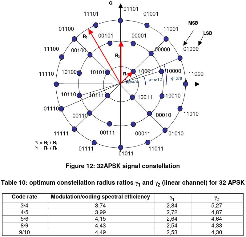
Please read section 5.4.4, titled Bit mapping into 32APSK. Pay attention to the number of points on each of the three rings and the two radius ratios that define the constellation's shape. Examine Figure 12 and Table 10.
The key features of the 32APSK constellation are:
- Structure: Three concentric rings.
- Inner ring (R1): 4 points
- Middle ring (R2): 12 points
- Outer ring (R3): 16 points
- Radius Ratios (): The shape is now defined by two ratios relative to the inner ring: and .
- Adaptive Geometry: Just like with 16APSK, Table 10 shows that these radius ratios are optimized for each FEC code rate to provide the best performance under different link conditions.
Your interest in Ham Radio and SDR has a direct link here. The QO-100 geostationary satellite, popular with radio amateurs, has a transponder that is well-suited for DVB-S2-like signals. Daniel Estévez, a radio amateur and software developer, wrote an excellent blog post detailing his project to build a narrowband modem for QO-100, where he explicitly uses the DVB-S2 32APSK constellation.
32APSK narrowband modem for QO-100 – Daniel Estévez
This post provides a practical application of the concepts we've just discussed, showing how a developer chose and implemented the 32APSK constellation for a real-world satellite link.
Please read the section titled Constellation. Notice how he directly references the DVB-S2 standard, the \gamma parameters, and the dependency on the coding rate. This is a perfect example of applying the standard in practice.
Bit Mapping in APSK
As with PSK, the way bits are mapped to symbols is not random; it's a form of Gray coding designed to minimize the number of bit errors that result from a symbol error. In APSK, the mapping is hierarchical.
- Most Significant Bits (MSBs): These bits generally determine which ring a symbol is on. An error in amplitude (mistaking one ring for another) is typically less probable than a small error in phase. Therefore, the MSBs, which carry more "weight," are assigned to the more robust amplitude selection.
- Least Significant Bits (LSBs): These bits determine the specific phase position of the symbol on a given ring.
If you look closely at the 16APSK diagram, you'll see this principle in action. The first two bits of the 4-bit symbol are primarily responsible for selecting the ring and quadrant, while the last two bits select the precise point within that group. This intelligent mapping ensures that the most likely errors (e.g., picking an adjacent point on the same ring) cause only a single bit to flip.
Conclusion
In this lesson, we moved beyond simple PSK to understand the more complex and powerful APSK modulations that are fundamental to modern satellite communication standards like DVB-S2.
Here are the main takeaways:
- APSK is a hybrid modulation that varies both amplitude and phase, providing a balance between the spectral efficiency of QAM and the power efficiency and non-linearity robustness of PSK.
- The DVB-S2 16APSK constellation uses two concentric rings (4 and 12 points), while 32APSK uses three rings (4, 12, and 16 points).
- A key feature of these constellations is their adaptive geometry. The ratios of the ring radii () are adjusted in conjunction with the FEC code rate to optimize performance for the current channel conditions.
- The bit-to-symbol mapping is hierarchical (a form of Gray coding) to ensure that the most probable symbol errors result in the minimum number of bit errors.
You have now reviewed the theory behind the I/Q representation and the key modulation schemes used in DVB-S2. In our next lesson, we will transition from theory to practice by firing up GNU Radio. You will learn how to use its signal processing blocks to generate and, more importantly, visualize the QPSK and 8PSK constellation diagrams we've discussed, taking the first hands-on step towards building and analyzing real DVB-S2 signals.