In our previous lesson, we established the foundational concept of representing RF signals using In-phase (I) and Quadrature (Q) components, which are conveniently handled as complex numbers in digital signal processing. Now, we will build directly upon that foundation to see how we can use this I/Q representation to encode digital information.
This lesson tackles our second learning outcome: Implement a QPSK and 8PSK modulator in Python or Rust that maps bit sequences to constellation points. We will move from the continuous nature of I/Q signals to the discrete world of digital modulation. You will learn to create specific, predefined I/Q points, each representing a unique sequence of bits. By the end of this lesson, you will have written code that performs one of the most fundamental operations in any digital communication system: turning raw bits into the symbols that are transmitted over the air.
From Bits to Symbols
In digital communications, we don't transmit individual bits one by one. Instead, we group them together and transmit a single "symbol" that represents that group of bits. A symbol is a specific, predefined state of the transmitted signal—a particular amplitude and phase—that the receiver is trained to recognize. By using a set of distinct symbols, we can represent bits with each symbol we send.
This idea is at the heart of spectrally efficient communication, a key goal in standards like DVB-S2. Let's start by formalizing the concept of a symbol.
The PySDR guide provides a concise introduction to the concept of symbols.
Please read the introductory section and the subsection titled Symbols. The key takeaway is that a symbol is a discrete unit that carries a certain number of bits. The more distinct states (symbols) we can create and reliably detect, the more bits we can pack into each transmission.
The collection of all possible symbols for a given modulation scheme is called a constellation. When we visualize these symbols on the 2D complex plane (with the x-axis as I and the y-axis as Q), we get a constellation diagram. This diagram is the master key for a digital signal, showing every possible I/Q value the transmitter can produce.
Encoding Information with Phase: Phase Shift Keying (PSK)
One of the simplest ways to create a set of distinct symbols is to keep the amplitude constant and vary only the phase. This technique is called Phase Shift Keying (PSK). In the I/Q plane, this means all our symbol points will lie on a circle centered at the origin.
The w2aew channel has an excellent video that recaps the I/Q concepts from our last lesson and provides a clear bridge to how these concepts are used in digital modulation like PSK.
#170: Basics of IQ Signals and IQ modulation & demodulation - A tutorial
This video provides a great conceptual walkthrough, connecting the idea of varying I and Q levels to the creation of discrete phase states used in PSK.
I recommend watching these three short segments: Phasor diagrams: This explains how the I/Q plane is used to represent the amplitude and phase of a signal as a single vector, which is fundamental to visualizing constellations. BPSK modulation: This shows the simplest form of PSK, where two phases (0° and 180°) are used to represent a single bit (0 or 1). QPSK modulation: This segment introduces Quadrature Phase Shift Keying (QPSK), which uses four phase states. Pay close attention to how the four points on the constellation diagram correspond to four unique combinations of I and Q values.
Quadrature Phase Shift Keying (QPSK)
As the video explained, QPSK is a cornerstone of digital modulation and is used extensively in DVB-S2. It uses four phases, typically separated by 90 degrees. Since there are four unique symbols, each symbol can represent bits of information.
The standard way to arrange these points is at 45°, 135°, 225°, and 315° on the unit circle. This has a convenient property: the I and Q values are simply combinations of (or for unit power).
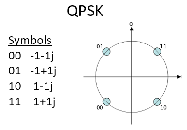
A crucial detail in this mapping is Gray coding. If you look at the bit labels around the circle (e.g., 00, 01, 11, 10), you'll notice that any two adjacent points differ by only a single bit. This is a deliberate design choice. If the receiver makes an error and chooses an adjacent symbol (the most likely type of error due to noise), it results in only a single bit error, not two.
Implementing a QPSK Modulator
Now, let's translate this into code. A modulator's job is to take a stream of bits, group them appropriately, and map each group to the corresponding complex number from the constellation. We'll implement this in both Python and Rust.
Python Implementation
Python, with libraries like NumPy and Matplotlib, is excellent for prototyping and visualizing DSP concepts. Here is a simple function to perform QPSK modulation.
import numpy as np
import matplotlib.pyplot as plt


# Gray-coded QPSK constellation map
# 00 -> -1 - 1j
# 01 -> -1 + 1j
# 10 -> +1 - 1j
# 11 -> +1 + 1j
# Note: The mapping in the image 58ce1 is different, but functionally equivalent.
# We use a more standard Gray-coded mapping here.
QPSK_MAP = {
    (0, 0): -1 - 1j,
    (0, 1): -1 + 1j,
    (1, 0): +1 - 1j,
    (1, 1): +1 + 1j,
}

def modulate_qpsk(bits):
    """
    Modulates a sequence of bits into QPSK symbols.

    Args:
        bits (list or np.ndarray): A sequence of bits (0s and 1s).

    Returns:
        np.ndarray: An array of complex QPSK symbols.
    """


    # Ensure the number of bits is even
    if len(bits) % 2 != 0:
        raise ValueError("Number of bits must be a multiple of 2 for QPSK.")

    symbols = []


    # Process bits in pairs
    for i in range(0, len(bits), 2):
        bit_pair = tuple(bits[i:i+2])
        symbols.append(QPSK_MAP[bit_pair])

    return np.array(symbols)


# --- Example Usage ---
# Generate a random bitstream
num_bits = 200
random_bits = np.random.randint(0, 2, num_bits)


# Modulate the bits
qpsk_symbols = modulate_qpsk(random_bits)


# Visualize the constellation
plt.figure(figsize=(6, 6))
plt.plot(np.real(qpsk_symbols), np.imag(qpsk_symbols), 'o')
plt.title('Generated QPSK Constellation')
plt.xlabel('In-Phase (I)')
plt.ylabel('Quadrature (Q)')
plt.grid(True)
plt.axhline(0, color='grey', lw=1)
plt.axvline(0, color='grey', lw=1)
plt.xticks([-1, 0, 1])
plt.yticks([-1, 0, 1])
plt.show()
This code defines a map for the constellation, groups the incoming bits into pairs, and looks up the corresponding complex symbol for each pair. The plot at the end visually confirms that our output symbols are correctly placed at the four constellation points.
Rust Implementation
Now for the Rust implementation. The logic is identical, but the syntax reflects Rust's focus on performance and type safety. We'll use the num_complex crate for complex number support.
To run this, you would add num_complex = "0.4" to the [dependencies] section of your Cargo.toml file.
use num_complex::Complex;

// Define a QPSK symbol map using an array for direct indexing.
// Index is (bit1 * 2 + bit0), e.g., '01' -> 1, '10' -> 2
// 0 (00) -> -1 - 1j
// 1 (01) -> -1 + 1j
// 2 (10) -> +1 - 1j
// 3 (11) -> +1 + 1j
const QPSK_MAP: [Complex<f64>; 4] = [
    Complex::new(-1.0, -1.0), // 00
    Complex::new(-1.0,  1.0), // 01
    Complex::new( 1.0, -1.0), // 10
    Complex::new( 1.0,  1.0), // 11
];

fn modulate_qpsk(bits: &[u8]) -> Result<Vec<Complex<f64>>, &'static str> {
    """
    Modulates a sequence of bits into QPSK symbols.

    Args:
        bits: A slice of u8, where each element is 0 or 1.

    Returns:
        A Vec of complex QPSK symbols or an error message.
    """
    if bits.len() % 2 != 0 {
        return Err("Number of bits must be a multiple of 2 for QPSK.");
    }

    // `chunks(2)` gives an iterator over 2-element slices of the input.
    let symbols: Vec<Complex<f64>> = bits
        .chunks(2)
        .map(|bit_pair| {
            // Convert the 2-bit pair into an index from 0 to 3
            let index = (bit_pair[0] * 2 + bit_pair[1]) as usize;
            QPSK_MAP[index]
        })
        .collect();

    Ok(symbols)
}

fn main() {
    // --- Example Usage ---
    // In a real application, these bits would come from a data source.
    let test_bits: Vec<u8> = vec![0, 0, 1, 1, 0, 1, 1, 0, 1, 1, 0, 0];

    match modulate_qpsk(&test_bits) {
        Ok(symbols) => {
            println!("Input bits: {:?}", test_bits);
            println!("Generated QPSK symbols:");
            for symbol in symbols {
                println!("  I: {:5.2}, Q: {:5.2}", symbol.re, symbol.im);
            }
        }
        Err(e) => eprintln!("Error: {}", e),
    }
}
This Rust code is more explicit about types and ownership but follows the same chunking and mapping pattern. The use of chunks(2) and map provides a functional, efficient way to perform the conversion.
Extending to 8-PSK
Increasing the data rate without increasing the bandwidth requires packing more bits into each symbol. The next logical step from QPSK (4-PSK) is 8-PSK, which uses eight phases. With eight distinct symbols, each can represent bits.

The symbols for an M-PSK constellation can be generated mathematically using Euler's formula:
where is the number of points (e.g., 8 for 8-PSK), is the symbol index (), and is an overall phase offset (often used to avoid placing a point on the I or Q axis). For 8-PSK, we can generate our 8 points by letting run from 0 to 7.
Implementing an 8-PSK Modulator
The implementation is a straightforward extension of our QPSK modulator. We just need to process bits in groups of three and use an 8-point constellation map.
Python Implementation
import numpy as np
import matplotlib.pyplot as plt


# Generate 8-PSK constellation using the mathematical formula.
# We add a pi/8 offset to match the typical Gray-coded constellation.
M = 8
phi = np.pi / M
PSK8_MAP_ARRAY = np.exp(1j * (2 * np.pi * np.arange(M) / M + phi))


# Gray code mapping for 3 bits
GRAY_CODE_MAP_8PSK = {
    (0, 0, 0): 0,
    (0, 0, 1): 1,
    (0, 1, 1): 2,
    (0, 1, 0): 3,
    (1, 1, 0): 4,
    (1, 1, 1): 5,
    (1, 0, 1): 6,
    (1, 0, 0): 7,
}

def modulate_8psk(bits):
    """ Modulates a bit sequence into 8-PSK symbols. """
    if len(bits) % 3 != 0:
        raise ValueError("Number of bits must be a multiple of 3 for 8-PSK.")

    symbols = []


    # Process bits in groups of three
    for i in range(0, len(bits), 3):
        bit_triplet = tuple(bits[i:i+3])
        map_index = GRAY_CODE_MAP_8PSK[bit_triplet]
        symbols.append(PSK8_MAP_ARRAY[map_index])

    return np.array(symbols)


# --- Example Usage ---
num_bits = 300
random_bits = np.random.randint(0, 2, num_bits)
psk8_symbols = modulate_8psk(random_bits)


# Visualize
plt.figure(figsize=(6, 6))
plt.plot(np.real(psk8_symbols), np.imag(psk8_symbols), 'o')
plt.title('Generated 8-PSK Constellation')
plt.xlabel('In-Phase (I)')
plt.ylabel('Quadrature (Q)')
plt.grid(True)
plt.axhline(0, color='grey', lw=1)
plt.axvline(0, color='grey', lw=1)
plt.axis('equal') # Ensure the circle looks like a circle
plt.show()
Rust Implementation
use num_complex::Complex;
use std::f64::consts::PI;

// Pre-calculate the 8-PSK constellation points at compile time.
const PSK8_MAP: [Complex<f64>; 8] = {
    const M: usize = 8;
    let mut map = [Complex::new(0.0, 0.0); M];
    // Gray code indices corresponding to binary 000, 001, ..., 111
    let gray_indices: [usize; 8] = [0, 1, 3, 2, 7, 6, 4, 5]; // Bit-reversed Gray code mapping

    let mut i = 0;
    while i < M {
        let phase = 2.0 * PI * (gray_indices[i] as f64) / (M as f64) + PI / (M as f64);
        map[i] = Complex::new(phase.cos(), phase.sin());
        i += 1;
    }
    map
};


fn modulate_8psk(bits: &[u8]) -> Result<Vec<Complex<f64>>, &'static str> {
    if bits.len() % 3 != 0 {
        return Err("Number of bits must be a multiple of 3 for 8-PSK.");
    }

    let symbols: Vec<Complex<f64>> = bits
        .chunks(3)
        .map(|bit_triplet| {
            // Convert the 3-bit triplet into an index from 0 to 7
            let index = (bit_triplet[0] * 4 + bit_triplet[1] * 2 + bit_triplet[2]) as usize;
            PSK8_MAP[index]
        })
        .collect();

    Ok(symbols)
}


fn main() {
    // --- Example Usage ---
    let test_bits: Vec<u8> = vec![0, 0, 0, 0, 0, 1, 0, 1, 0, 1, 1, 1];

    match modulate_8psk(&test_bits) {
        Ok(symbols) => {
            println!("Input bits: {:?}", test_bits);
            println!("Generated 8-PSK symbols:");
            for symbol in symbols {
                println!("  I: {:5.2}, Q: {:5.2}", symbol.re, symbol.im);
            }
        }
        Err(e) => eprintln!("Error: {}", e),
    }
}
This completes the implementation part of our goal. You now have functional QPSK and 8-PSK modulators in two powerful languages.
Conclusion
In this lesson, we made the crucial leap from representing an analog signal with I/Q values to using those values to encode digital data. We saw that a digital modulator is essentially a mapping function from groups of bits to points on the complex I/Q plane.
Here are the key takeaways:
- Symbols and Constellations: We group bits into symbols, and the set of all possible symbols forms a constellation, which is visualized on an I/Q diagram.
- Phase Shift Keying (PSK): A modulation family that encodes information in the phase of the carrier, corresponding to points on a circle in the I/Q plane.
- QPSK and 8-PSK: QPSK uses four points to encode 2 bits per symbol, while 8-PSK uses eight points to encode 3 bits per symbol, offering a higher data rate.
- Gray Coding: A specific bit-to-symbol mapping that minimizes bit errors by ensuring adjacent constellation points differ by only one bit.
- Implementation: A modulator can be implemented as a simple lookup table or dictionary that maps bit groups to their corresponding complex I/Q values.
So far, we have only looked at constellations where all points have the same amplitude. However, to achieve even higher spectral efficiencies, modern standards like DVB-S2 also vary the amplitude. In our next lesson, we will explore these more advanced schemes, specifically the ring-based constellations of 16APSK and 32APSK, which combine both amplitude and phase modulation.