Welcome to your first lesson on the path to understanding DVB-S2X and MF-TDMA. Before we can dive into the complexities of satellite communication frames and access schemes, we must begin with the fundamental language of modern digital radio: the representation of signals. Your background in Electronics and Communications Engineering will be a great asset here, as we'll be touching on concepts like oscillators, mixers, and filters, but framed in the context of software-defined radio (SDR) and digital communications.
This lesson addresses our first learning outcome: Explain how a bandpass signal is represented using in-phase (I) and quadrature (Q) components. Mastering this concept is crucial, as the I/Q data format is the bedrock upon which all the advanced digital modulation schemes used in DVB-S2 are built. It's the standard way that signals are processed in systems from your mobile phone to the satellite terminals you work with, and it's the data you'll manipulate directly when using your HackRF One with GNU Radio.
The Challenge: Controlling a High-Frequency Signal
At its core, a radio signal transmitted through the air—a bandpass signal—is a high-frequency sine wave. We can describe it with the familiar equation:
Here, is the high-frequency carrier (e.g., in the GHz range for satellite links), while is the amplitude and is the phase. To transmit information, we modulate or vary and according to the data we want to send.
While controlling amplitude is relatively straightforward in RF circuits, directly and rapidly controlling the phase of a high-frequency oscillator is difficult and expensive. This practical engineering challenge led to a more elegant solution: representing the signal in a way that avoids direct phase manipulation altogether.
The Solution: In-Phase and Quadrature Components
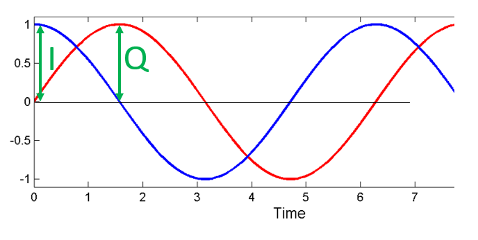
The solution lies in a fundamental trigonometric identity. Any sinusoid with an arbitrary phase can be decomposed into the sum of a cosine wave and a sine wave of the same frequency. These two waves are "in quadrature," meaning they are 90 degrees out of phase with each other.
To understand this better, let's dive into our first resource.
IQ Sampling | PySDR: A Guide to SDR and DSP using Python
The following reading from the PySDR guide provides a clear mathematical and visual introduction to how two orthogonal sinusoids can be combined to represent any arbitrary amplitude and phase.
In the article, please read the section on Quadrature Sampling. Focus on how the trig identity is used to represent a single sinusoid with a specific amplitude and phase as the sum of a cosine and a sine wave. Pay close attention to the definition of the I and Q components and how they act as simple amplitude scalers. The text also explains the practical advantage of this method: it's easier to control two amplitudes (I and Q) in hardware than to directly manipulate a signal's phase.
As the reading explains, we can represent our bandpass signal as:
Where:
- is the In-phase component. It's the amplitude scaling the cosine (0° phase reference) carrier.
- is the Quadrature component. It's the amplitude scaling the sine (90° phase reference) carrier.
The original amplitude and phase are now encoded in these two new amplitude values:
We have successfully transformed the problem of modulating one amplitude and one phase into the much easier engineering problem of modulating two separate amplitudes, and .
The Receiver's Dilemma: Why Two Components are Essential
This I/Q representation is not just a convenience for the transmitter. It is essential for the receiver to correctly interpret the signal's phase. Imagine you only tried to measure the projection of the signal onto the cosine axis. Could you uniquely determine the phase?
The following video provides an excellent visual explanation of why a single measurement is ambiguous and how the second (quadrature) measurement resolves this ambiguity completely.
How to Get Phase From a Signal (Using I/Q Sampling)
This short video explains why sampling just one component of the signal isn't enough to determine its phase and how using two components—I and Q—solves the problem.
Please watch the section from the explanation. The first part shows why sampling a single sinusoid leads to phase ambiguity. The second part demonstrates how sampling both a cosine and a sine component at the same time provides a unique two-dimensional vector that precisely identifies the signal's phase.
As the video shows, the I and Q values for a given point in time form a 2D vector. The magnitude of this vector corresponds to the signal's amplitude (), and its angle corresponds to the signal's phase (). This two-dimensional representation ensures that every unique combination of amplitude and phase has a unique coordinate.
Hardware Implementation: The I/Q Modulator
The principles we've discussed are directly implemented in RF hardware. An I/Q modulator is a circuit designed specifically to generate a bandpass signal from I and Q inputs. Given your ECE background, the structure of this circuit should be quite intuitive.
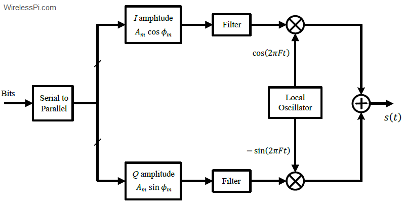
The diagram shows:
- A Local Oscillator (LO) that generates the high-frequency carrier wave.
- A 90-degree phase shifter that splits the LO signal into cosine and sine components.
- Two mixers (which act as multipliers) that multiply the I and Q baseband signals with the cosine and sine carriers, respectively.
- A summer that combines the two modulated carriers into a single RF output.
The following video gives a fantastic hands-on demonstration of a real I/Q modulator, which will help solidify your understanding of how it works in practice.
#262: IQ Modulator Basics: Operation, measurements, impairments
This theoretical block diagram comes to life in actual RF hardware. The following video demonstrates a real I/Q modulator circuit. Watching it in action provides a strong intuition for how varying the I and Q inputs directly controls the output RF signal.
First, watch the brief explanation of the modulator's block diagram, which you'll recognize from the diagram above. Then, jump to the hands-on demonstration from the demonstration. Observe how applying a simple DC voltage to the I input results in an output in phase with the I-carrier (cosine), and applying it to the Q input results in an output in phase with the Q-carrier (sine). Most importantly, notice how applying voltage to both allows the creation of any intermediate phase.
From RF Signal to Digital Data: Baseband, Downconversion, and Complex Numbers
So far, we have established that a real-world, high-frequency bandpass signal can be constructed from two lower-frequency amplitude signals, I and Q. These I and Q signals are known as the baseband signal. They contain all the information but exist "around 0 Hz" before being mixed up to the carrier frequency for transmission.
At the receiver, the reverse process, called downconversion, happens. The incoming high-frequency RF signal is mixed with the receiver's local oscillator (cosine and sine versions) and then low-pass filtered to extract the original I and Q baseband signals. This is precisely what your HackRF One does internally when you tune it to a specific frequency.
In the digital world of SDR and software processing (using Python, Rust, or GNU Radio), it's cumbersome to always deal with two separate arrays of numbers for I and Q. Instead, they are almost universally combined into a single stream of complex numbers, where I is the real part and Q is the imaginary part:
This is not just a notational convenience; it makes the mathematics of many signal processing operations, like filtering and Fourier transforms, significantly more elegant.
The final reading from the PySDR guide ties these crucial concepts of baseband signals and complex representation together.
IQ Sampling | PySDR: A Guide to SDR and DSP using Python
Now that we understand what I and Q components are, let's connect them to the digital representation used in SDR. This reading explains the link between I/Q and complex numbers, the distinction between baseband and bandpass signals, and the process of downconversion.
Please read the following sections: Start with Complex Numbers, focusing on how a complex number's real and imaginary parts map directly to the I and Q components. Next, read about the Receiver Side and Carrier and Downconversion. Pay attention to how a receiver uses two ADCs to sample the I and Q branches and how the downconversion process shifts the high-frequency RF signal to baseband, making it possible to sample with much slower (and cheaper) ADCs. Finally, read Baseband and Bandpass Signals to solidify the distinction. The key takeaway is that baseband signals, as processed in software, are complex, while the bandpass signals transmitted over the air are always real.
Conclusion
In this lesson, we have refreshed the fundamental concept of I/Q signal representation. You should now be able to explain how any bandpass signal can be described by its in-phase (I) and quadrature (Q) components.
Here are the key takeaways:
- A bandpass signal's amplitude and phase can be represented by two separate amplitudes, and , that modulate a pair of orthogonal carriers (cosine and sine).
- This method simplifies RF hardware design, as controlling amplitudes is easier than directly controlling phase.
- At the receiver, both I and Q components are required to unambiguously determine the signal's original phase and amplitude.
- The and signals are the baseband representation of the signal. In digital signal processing and SDR, they are stored and manipulated as a single stream of complex numbers .
In our next lesson, we will put this knowledge to immediate use. We will see how digital modulation schemes like QPSK and 8PSK, which are central to DVB-S2, work by mapping sequences of bits to specific coordinates on a 2D plane.