Hello! Welcome to the next lesson in our course on high-field magnet design.
In our previous session, we built a crucial bridge between the electromagnetic and thermal worlds. You learned how to set up a coupled simulation to predict the temperature evolution, , in a coil during a pulse, driven by the Joule heating from the current, . Today, we will add the final, critical piece to our multi-physics model: mechanics.
This lesson directly addresses the learning outcome: Perform a structural mechanics simulation to calculate stress and strain distributions from Lorentz forces and thermal expansion. We will take the outputs from our previous simulations—the current density and temperature profiles—and use them as inputs to determine how the magnet mechanically responds to the extreme conditions of a pulse. Understanding these stresses is the key to designing a magnet that doesn't destroy itself.
Let's look at the complete picture. The flowchart below shows how the different physics domains are interconnected in a full magnet simulation. In previous lessons, we've covered the electrical, magnetic, and thermal components. Today, we focus on the final step: the structural analysis.
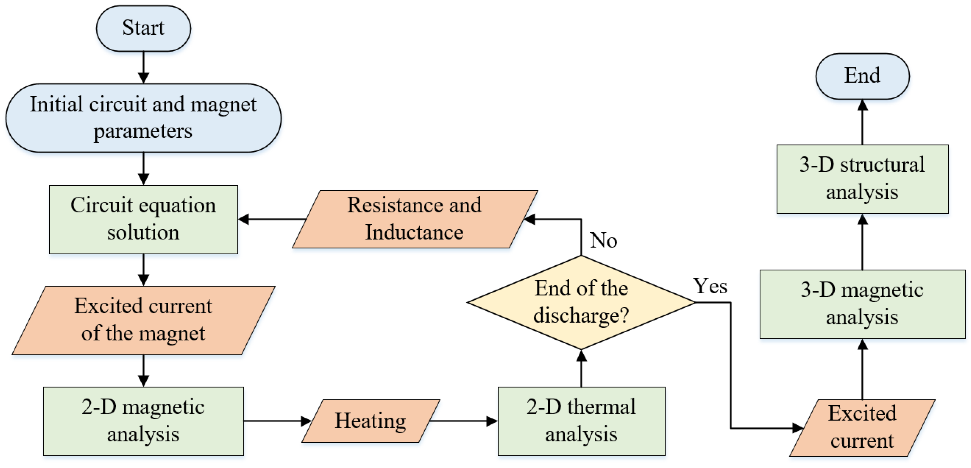
1. From Physics to Mechanical Loads
A structural simulation requires "loads"—the forces and effects that cause the object to deform. For a pulsed magnet, these loads come directly from the electromagnetic and thermal physics we've already studied.
Lorentz Forces
The primary load is the Lorentz force, generated by the interaction of the current in the windings with the magnetic field. The force density (force per unit volume) is given by:
In a solenoid, this force is directed radially outwards and axially inwards (compressing the coil), generating immense pressure. In a Finite Element Method (FEM) simulation, this is not applied as a simple external force but as a body force, a force that acts on the entire volume of the conducting elements. The software first solves for from and then uses both to compute the force field at every point within the conductor for each time step.
Thermal Expansion
The second major load is thermal expansion. As the coil heats up from Joule losses, the material expands. The resulting thermal strain, , for an isotropic material is:
where is the temperature-dependent coefficient of thermal expansion and is the initial, stress-free temperature. This effect is critical. The inner windings heat up the most and want to expand, but they are confined by the cooler, outer reinforcement layers. This mismatch in expansion creates significant internal stresses, which are superimposed on the stresses from the Lorentz force.
2. Describing Large Deformations: A Deeper Look at Strain
In your introductory mechanics courses, you encountered strain as . This is the infinitesimal strain tensor, which is only accurate for very small deformations and rotations. Given that pulsed magnets can experience significant plastic deformation, a more robust framework is needed for accurate modeling. Your physics and math background will be useful for appreciating this more rigorous approach.
To properly describe how a material deforms, continuum mechanics introduces the deformation gradient tensor, . It relates a vector in the undeformed material to its new orientation and length in the deformed material. A key insight is that contains information about both pure deformation (stretching/shearing) and rigid body rotation. To isolate the pure deformation, we use a polar decomposition:
Here, is a rotation matrix and is the symmetric right stretch tensor, which purely describes the stretching of the material.
From this, we can define strain tensors that are suitable for large deformations. One of the most important is the Green-Lagrange strain tensor, :
where is the identity tensor. The key properties of are:
- It is zero for any rigid body motion (translation or rotation), making it a pure measure of deformation.
- For small deformations, it reduces to the familiar infinitesimal strain tensor.
To solidify these concepts, which are fundamental to the algorithms used in FEM solvers, please watch the following video.
Different Strain Tensors Explained: Cauchy-Green VS Green-Lagrange VS Euler-Almansi
The video 'Different Strain Tensors Explained' by Dr. Simulate provides an excellent step-by-step derivation of the strain tensors used in large-deformation mechanics. It clearly explains why the simple strain tensor is insufficient and builds up the concepts of the deformation gradient and the Green-Lagrange tensor.
Please watch the video from the beginning to 20:59. Focus on these key ideas: Why we need more than one strain measure: Understand the distinction between stretch and strain and why simple measures can be ambiguous in 3D (00:00 - 02:26). The Deformation Gradient (F) and Rotational Invariance: Grasp why F itself is not a pure measure of deformation and how the right stretch tensor (U) solves this problem (02:58 - 07:08). Lagrangian vs. Eulerian Tensors: This is a key concept. Understand that Lagrangian tensors (like U and C) are tied to the undeformed body, which makes them ideal for defining material constitutive laws (07:08 - 11:36). Cauchy-Green and Green-Lagrange Tensors: See how the right Cauchy-Green tensor C = F^T F is computationally simpler than U, and how the Green-Lagrange tensor E = 1/2(C - I) is constructed to be zero in the undeformed state, making it a true 'strain' tensor (12:01 - 20:59).
This theoretical foundation is what allows FEM software to accurately calculate strains and, consequently, stresses, even when the magnet coil is pushed into plastic deformation.
3. A Practical Guide to Structural Simulation
Let's now walk through the process of setting up a structural simulation for a pulsed magnet coil. We will use the detailed technical report by M.G.N.M. Oudendijk, which analyzes a high-field magnet using the MARC finite element program, as our guide. The principles discussed are applicable to any modern FEM package.
Mechanical aspects of high-field magnet coil-systems
The report 'Mechanical aspects of high-field magnet coil-systems' is a masterclass in the practical application of FEM to magnet design. It details the entire modeling process, from discretizing the coil to analyzing the results, including the crucial effects of thermal loading.
We will be referring to specific sections of this report. For now, familiarize yourself with its structure. We'll be focusing on Sections 3.2, 3.3, 3.4, and 3.7. I will guide you through the key points.
Step 1: Discretization and Geometry (Section 3.2)
The first step is to create a model. Given the cylindrical nature of a solenoid, an axisymmetric 2D model is often sufficient and computationally much cheaper than a full 3D model.
- The model represents a cross-section of the coil.
- Symmetry about the mid-plane is used, so only half of the cross-section is needed.
- The mesh is refined in areas where high stress gradients are expected (e.g., near the inner bore).
This is Figure 3.2.1 from the Oudendijk report, showing the axisymmetric mesh of a single coil. Note the symmetry about the mid-plane and the axis of rotation.
Step 2: Material Modeling (Section 3.3)
This is the most complex part. A coil is not a monolithic object; it's a composite of conductor (e.g., copper) and insulation (e.g., epoxy resin).
- Composite Behavior: The report describes a sophisticated method where the elastic properties of the winding/insulation composite are calculated using models like Halpin-Tsai.
- Plasticity: Plastic deformation is assumed to be dominated by the conductor. To check for this, the stresses in the winding material are calculated from the overall composite stresses.
- Yield Criterion: Plasticity begins when the stress state reaches a critical level. This is determined by a yield criterion. The most common for metals is the von Mises yield criterion. It combines the different stress components into a single equivalent stress, . The material yields when exceeds the material's yield strength, .
Step 3: Loads and Boundary Conditions (Section 3.3)
- Boundary Conditions: An axial displacement of zero is enforced at the mid-plane due to symmetry.
- Loads: The Lorentz forces are applied as body forces, scaled by the fraction of conductor in each element. The thermal load is applied by defining the temperature of the elements from the thermal simulation.
Step 4: Analyzing the Results (Section 3.4)
The simulation's output is a rich dataset of stress and strain tensors at every point in the model.
- Stress Components: We can plot individual components like tangential (hoop) stress, radial stress, and axial stress.
- Equivalent Stress: The von Mises stress is plotted to see which regions of the coil have yielded (i.e., where ).
- Deformation: We can visualize how the coil shape changes under load.
Let's examine some typical results. The figures below, from the Oudendijk report and another study, show the calculated stress distribution and resulting deformation.
Figure 3.4.1 from the Oudendijk report. It shows the calculated stress components in the mid-plane at maximum field (a) and the residual stresses after the pulse (b). Notice the high tangential (hoop) stress and compressive radial stress.
Test your understanding!
Looking at Figure 3.4.1a from the Oudendijk report (the image above), please answer the following:
- Where does the peak tangential (hoop) stress occur? Is it tensile or compressive?
- The radial stress is compressive almost everywhere but goes to zero at the innermost radius (0.1 m). Why does this make physical sense?
Show answer
- The peak tangential stress (solid green line) occurs around a radius of 0.13 m. It is positive, indicating it is a tensile stress. This is the "hoop stress" trying to pull the coil apart.
- The radial stress represents the pressure between adjacent layers of windings. As you move outwards, each layer is pushed upon by the layer inside it, creating compressive radial stress. However, the very innermost layer has nothing inside it to push on it, so the radial stress at the inner boundary must be zero.
4. Coupling Thermal and Mechanical Effects
Now we combine everything. The total strain at any point is the sum of the elastic strain , plastic strain , and thermal strain . The structural solver must account for all of these simultaneously.
Section 3.7.3 of the Oudendijk report investigates exactly this coupling for a steel-reinforced coil.
- The winding material heats up and tries to expand ().
- The massive steel reinforcement remains much cooler and does not expand as much.
- The result is a significant increase in the compressive radial stress between the coil and the shield. The hot coil pushes outwards against the cold shield.
This is a perfect example of a coupled multi-physics problem where thermal expansion and Lorentz forces combine to determine the final stress state. A real-world example is seen in the "Foil Coil" paper, which uses FEA to visualize this stress transfer.
A novel pulsed magnet for magnetic linear birefringence ...
The paper 'A novel pulsed magnet for magnetic linear birefringence...' presents a practical case study. It describes the design of a 'Foil Coil' and uses FEA to analyze the mechanical stresses.
Please read Sections III.B 'Realization' and look closely at Figure 3. This section highlights how Lorentz forces create 'huge stress' and how FEA models are used to visualize the transmission of these forces to the Zylon reinforcement and the hoop stress in the coil ends.
The FEA images in this paper (Figure 3) clearly show how the internal forces are transmitted through the copper foil and into the external reinforcement, providing a tangible example of the stress distributions we've been discussing.
Conclusion
You have now completed the full multi-physics simulation chain for designing a pulsed magnet. We started with the electrical circuit, moved to the magnetic and thermal fields, and have now used those results to perform a structural analysis.
Key Takeaways:
- Structural simulations of pulsed magnets are driven by two primary loads: Lorentz forces (applied as body forces) and thermal expansion (applied as an initial strain).
- For accurate analysis of large deformations, advanced strain measures like the Green-Lagrange tensor are used, which are rotationally invariant.
- Practical FEM modeling involves simplifying the geometry (e.g., axisymmetry) and using sophisticated material models that account for the composite nature of the coil and plastic deformation (e.g., via the von Mises yield criterion).
- The output of the simulation provides detailed stress and strain distributions, allowing engineers to identify high-stress regions and assess whether the magnet will survive the pulse.
Next Lesson Preview:
So far, our simulations have been for analysis—predicting the performance of a given design. The next step is to use this predictive power for synthesis—creating a better design. In the next lesson, we will learn how to formulate a design optimization problem with a clear objective function and constraints. We will explore how to use algorithms to automatically search for an optimal coil geometry that maximizes performance (like the central field) while respecting physical limits (like the maximum allowable stress).