Hello! Let's dive into the next crucial step in our journey through numerical modeling for high-field magnets.
In the last lesson, we focused on the "electro-magnetic" part of the puzzle. You learned the standard workflow for setting up a simulation in a commercial FEM package to calculate the magnetic field distribution, , for complex coil geometries.
Today, we address the learning outcome: Set up a coupled electromagnetic-thermal simulation to calculate the temperature evolution in a coil during a pulse. We'll bridge the gap from a static field calculation to a dynamic, transient simulation where the immense currents of a pulse generate significant heat. Understanding and predicting this temperature rise is paramount, as it directly impacts the coil's resistance, attainable peak field, and mechanical integrity—a core challenge in pulsed magnet design.
1. The Physics of Multi-Physics Coupling
At its heart, a coupled electromagnetic-thermal simulation solves two sets of physical laws simultaneously and allows them to influence each other. Your background in physics and mathematics will make the governing equations familiar.
- Electromagnetics: Maxwell's equations, solved in a transient form, determine the evolution of the current density throughout the conductor.
- Thermodynamics: The heat diffusion equation governs the temperature distribution : where is the mass density, is the specific heat capacity, is the thermal conductivity, and is the volumetric heat source.
The Coupling Mechanism:
The two physics domains are not independent. They are linked through two critical relationships that form an iterative feedback loop, as illustrated in the flowchart below.

-
Electromagnetics Thermal (The Heat Source): The current flowing through the resistive conductor generates Joule heat. This becomes the source term in the heat equation:
where is the electrical resistivity.
-
Thermal Electromagnetics (The Feedback): The temperature change is not just a result; it's an input. The material properties of the conductor, most importantly its electrical resistivity (), but also its thermal conductivity () and specific heat capacity (), are strong functions of temperature.
As the coil heats up, its resistance increases. For a given circuit, this changes the current pulse itself, typically damping it more strongly. The FEM solver accounts for this at each time step, creating a fully coupled, dynamic simulation.
2. A Practical Guide to Setting Up a Coupled Simulation
Let's translate this theory into the practical steps you would take in a commercial FEM package like COMSOL Multiphysics. The following video demonstrates a coupled simulation for induction heating. While the application is different, the core physics—an electromagnetic field generating heat in a conductor—and the software workflow are identical to what's needed for a pulsed magnet.
Induction heating simulation of an iron bar using Comsol Multiphysics
This video, 'Induction heating simulation of an iron bar using Comsol Multiphysics' by Jaf-Science, provides an excellent, step-by-step walkthrough of setting up a coupled electromagnetic-thermal simulation.
Please watch the video, focusing on these key segments which map directly to our problem: Physics and Study Selection (00:29 - 01:38): Notice the selection of the 'Induction Heating' interface, which automatically combines the 'Magnetic Fields' and 'Heat Transfer' physics. The video uses a 'Frequency-Transient' study for a sinusoidal input. For a pulsed magnet, you would select a fully 'Time Dependent' study to model the non-sinusoidal pulse shape. Defining Temperature-Dependent Materials (04:08 - 07:35): This is the most critical part for the feedback loop. Observe how interpolation functions are used to define electrical conductivity, thermal conductivity, and specific heat as functions of temperature, based on tabulated data. This is precisely how you would model a real conductor like copper. Physics Setup & Coupling (08:13 - 11:26): The video shows how the coil is excited with a current. Critically, it points out that the Joule heating source is automatically included in the heat transfer physics—this is the 'coupling'. It also shows how to add thermal boundary conditions like convection and radiation, which model cooling. Solver Settings (16:28 - 19:56): Pay attention to the setup of the time-dependent solver, including the time steps and how a 'Stop Condition' can be added (e.g., stop the simulation when the coil reaches a certain peak temperature). Post-processing (21:00 - 23:53): See how the final results are visualized—a temperature map on the geometry and a plot of the current density, which clearly shows the skin effect. This is the ultimate output of the simulation.
This walkthrough gives you a concrete mental model of the entire process, from defining the problem to visualizing the results.
3. Application to Pulsed Magnets: A Case Study
Now, let's connect this general workflow to the specific case of a pulsed magnet. The current in a capacitor-driven magnet isn't a steady sinusoid; it's a transient pulse, typically a damped sine wave.
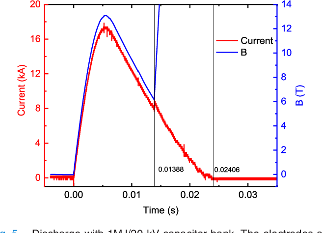
A research paper analyzing thermodynamic processes in a wire-wound pulsed coil provides an excellent example of the results of such a coupled simulation. While they used a different tool (MATLAB/Simulink), the physical model is the same.
The Influence of Pulsed Magnet Heating on Maximal Value ...
This paper, 'The Influence of Pulsed Magnet Heating on Maximal Value ...', investigates the exact problem we are studying. It models the thermal effects during a pulse and compares the simulation to experimental data.
Please read Sections 2, 3, and 4 (pages 95-97). Focus on the figures and the concepts they illustrate: Adiabatic Heating: Section 2 notes that for a rapid pulse (a few milliseconds), the heating process is nearly adiabatic. This means heat is generated faster than it can diffuse away. Your FEM simulation can test this assumption by comparing the temperature rise with and without thermal diffusion enabled. Iterative Calculation: The paper describes a simulation loop where, at each time step, Joule heat is calculated, the temperature is updated, and the new resistance R(T) is used for the next step. This is a conceptual description of what COMSOL does automatically within its transient solver. Figure 4: This is a key result. It compares the simulated current pulse with and without Joule heating. You can clearly see that including thermal effects (red dashed line) leads to a lower peak current and faster decay, because the increased resistance provides more damping to the RLC circuit. Figure 5b: This plot quantifies the impact on performance, showing the reduction in magnetic field caused by the heating. This directly demonstrates why this coupled simulation is so vital for accurate magnet design. Validation: Figure 6 compares the simulated magnetic field with experimentally measured values, showing reasonable agreement. This step of validating the model against reality is fundamental to the engineering process.
This paper perfectly encapsulates the "why" behind this lesson. The coupled simulation isn't just a complex academic exercise; it's a predictive tool essential for understanding and optimizing the real-world performance of a pulsed magnet.
Test your understanding!
You are setting up a coupled electromagnetic-thermal simulation for a copper coil that will be pulsed from an initial temperature of 77 K (LN2 temperature). You find a datasheet for copper that lists its electrical resistivity at 77 K and 300 K. How would you implement this information in the FEM software, and why is a simple linear interpolation between these two points likely insufficient for a high-fidelity simulation?
Show answer
Implementation:
In the FEM software, I would go to the material properties for copper and define the electrical resistivity not as a single constant value, but as a function of temperature. I would use the software's "Interpolation Function" feature. I would create a table with two data points: (T1=77 K, rho1=value) and (T2=300 K, rho2=value). The software would then use this table to look up the resistivity based on the calculated temperature at each point in the coil at each time step.
Insufficiency of Linear Interpolation:
A simple linear interpolation between two distant points (77 K and 300 K) is likely insufficient because the resistivity of copper (and most metals) is highly non-linear, especially at cryogenic temperatures. The resistivity-temperature curve (governed by electron-phonon scattering) flattens out at very low temperatures (approaching the residual resistivity) and has a different slope at higher temperatures. Using only two points would miss this curvature, leading to significant errors in the calculated resistance, Joule heating, and final temperature, particularly if the coil's temperature evolves through the intermediate range (e.g., 100-200 K) during the pulse. For high-fidelity results, a table with more data points covering the entire expected operating temperature range is necessary.
4. Advanced Models and Validation
The principles we've discussed scale to even more complex systems. For instance, high-temperature superconductor (HTS) magnets involve tapes with multiple layers (superconductor, copper, substrate, etc.). Simulating a quench (the transition from superconducting to normal resistive state) requires an even more detailed model.
The paper "Electromagnetic-thermal finite element model coupled to..." (Resource ID: LINK), which you can look at for further insight, details such a model. Its Figure 6 provides a sophisticated view of the TEFEM-ECM (Thermo-Electro-Magnetic Finite Element Model coupled to an Electrical Circuit Model). It shows how currents are redistributed among the different layers of an HTS tape as the temperature rises during a pulse, a phenomenon known as current sharing. The paper's ultimate goal, as seen in its Figures 16 through 21, is to compare simulation outputs (current, voltage, temperature) with real experimental data, reinforcing the critical role of experimental validation.
Conclusion
Today, we've added a critical layer of physics to our simulation toolkit. You now understand the principles and practical steps for creating a coupled simulation that predicts the thermal evolution of a coil during a pulse.
Key Takeaways:
- Coupled electromagnetic-thermal simulations are essential for predicting temperature rise and its impact on pulsed magnet performance.
- The simulation is built on a feedback loop: generates heat , and the resulting temperature changes the material properties (especially ), which in turn affects .
- The practical workflow involves using a coupled physics interface, defining temperature-dependent material properties using interpolation tables, and running a transient (time-dependent) study.
- The results of such simulations provide crucial design insights, predicting the peak temperature, the reduction in peak field due to heating, and allowing for validation against experimental data.
Next Lesson Preview:
We have now mastered the calculation of , , and . This completes the electromagnetic and thermal analysis. What's next? The immense forces and temperature gradients generate mechanical stress. In our next lesson, we will perform a structural mechanics simulation to calculate stress and strain distributions from Lorentz forces and thermal expansion, adding the final piece to our multi-physics model.