Hello! Welcome back to our series on the design of high-field magnets.
In our last lesson, we focused on a critical safety system: the dump resistor, designed to dissipate the capacitor bank's energy in a controlled manner during a fault or shutdown. We saw how a simple RC circuit can be engineered to handle immense energy safely.
Today, we transition from dissipating energy to precisely controlling it to create sophisticated magnetic field profiles. While a simple sinusoidal pulse is the default output of an LCR circuit, many experiments demand more complex pulse shapes. This lesson directly addresses the learning outcome: Analyze multi-stage capacitor discharge systems with sequential triggering to generate complex pulse shapes. We will explore the "why" and "how" of generating non-sinusoidal pulses, such as flat-top and double pulses, by orchestrating the discharge of multiple capacitor stages.
1. The Need for Complex Pulse Shapes
A standard capacitor discharge produces a brief, quasi-sinusoidal magnetic field pulse. While useful, this has limitations:
- Short Time at Peak Field: The field is only at its maximum for an instant. For experiments that require a finite time to perform a measurement at a specific field (like NMR or optical spectroscopy), this is a major constraint.
- Dynamic Field: The constantly changing field () induces large eddy currents and pickup voltages in the sample and measurement apparatus, which can heat the sample and corrupt sensitive measurements.
- Single Event: Some experiments, like pump-probe studies, require an initial pulse to excite a system, followed by a second pulse to probe its evolution after a specific delay.
To overcome these issues, magnet designers have developed techniques to generate complex pulse shapes, most notably:
- Flat-Top Pulses: Where the magnetic field is held nearly constant for several milliseconds at or near its peak.
- Multi-Pulses: Where two or more distinct pulses are generated within a short time frame.
The key to achieving these profiles lies in moving beyond a single capacitor bank and treating the power supply as a collection of modular energy sources that can be triggered sequentially.
2. General Principle: Sequential Triggering
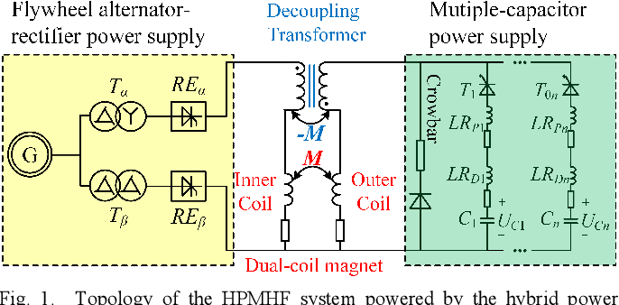
Large capacitor banks, like the one at the Dresden High Magnetic Field Laboratory, are built from many individual modules. While they can be discharged simultaneously to produce the maximum current, they can also be triggered independently.
Nuclear magnetic resonance spectroscopy in pulsed ...
The following paper mentions this concept explicitly. While we won't read it in detail, it confirms the fundamental idea we'll be exploring.
In the 'Future perspectives' section, find the paragraph starting 'Further improvements...'. The author notes that one approach could involve 'the use of several capacitor units, triggered sequentially to generate multiple maxima of the pulsed field at successive times.'
This is the core principle. By using separate high-current switches (like thyristors or ignitrons) for different capacitor modules or banks, a control system can fire them at precisely timed intervals, allowing their individual current contributions to sum together in the magnet coil over time.
3. Generating a Flat-Top Pulse
Let's examine how sequential triggering can produce a stable, flat-top field. This is crucial for experiments like nuclear magnetic resonance (NMR), where a constant field is required to satisfy the resonance condition.
Method 1: Cascaded H-Bridge Topology
One powerful method uses multiple power converter stages, each with its own capacitor, connected in parallel to the magnet.
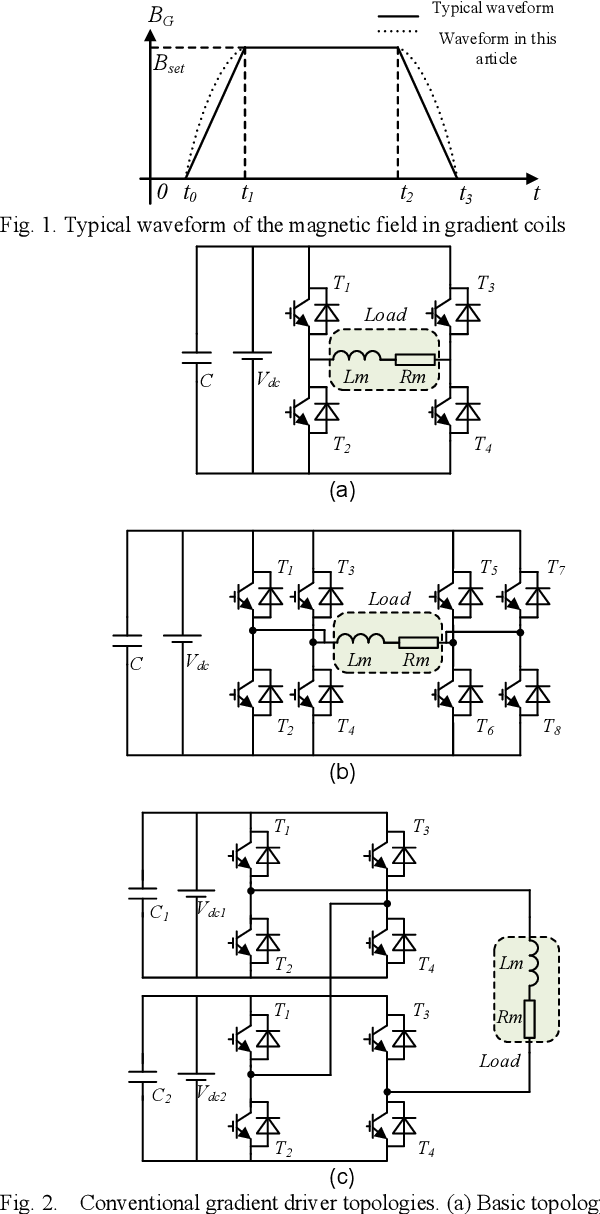
Look closely at topology (c) in the image above. It shows two separate capacitor banks (C1, C2) and two H-bridges (sets of switches T1-T4 and T5-T8) driving the same load (the magnet, Lm and Rm). A trapezoidal pulse, like the one shown in the "Typical waveform" diagram, can be generated with the following sequence:
- Ramp-Up: The control system triggers switches T1 and T4 in the first H-bridge. Current flows from C1 into the magnet, and the magnetic field begins to rise.
- Hold (Flat-Top): Just as the current from C1 is about to peak and roll over, the control system triggers switches T5 and T8 from the second H-bridge. This injects a new surge of current from C2, timed to counteract the decay from the first stage and hold the total current—and thus the magnetic field—at a relatively constant level. By using more stages or sophisticated pulse-width modulation (PWM) within the stages, this "hold" phase can be made very flat.
- Ramp-Down: Once the flat-top duration is complete, the switches are opened. The current then decays through crowbar diodes (not shown in this simplified diagram, but discussed in a previous lesson) or is actively ramped down by reversing the voltage.
This modular approach is highly flexible and can be scaled to create longer flat tops or more complex shapes.
Method 2: Main Pulse with Active Compensation
Another elegant method uses a secondary, smaller coil placed inside the main magnet.
Nuclear magnetic resonance spectroscopy in pulsed ...
This paper on NMR in pulsed fields describes the use of a compensation coil to achieve a highly stable flat-top field. Let's see how it works.
Please read the final paragraph of the section 'II.1 Pulsed-field generation', starting with 'Another method for achieving reproducible, well-controlled field profiles...'. Pay close attention to Figure 8 and its description.
As you read, this technique involves two separate power supplies and coils:
- A main coil is powered by a large capacitor bank to generate the bulk of the field (>99%).
- A smaller compensation coil is powered by a separate, highly controllable power supply.
A sensor measures the magnetic field in real time. A feedback loop compares the measured field to the target flat-top value and dynamically adjusts the current in the compensation coil to cancel out any deviations. This system acts like a fine-tuning knob, adding or subtracting a small amount of field to keep the total field exceptionally constant, achieving variations as low as 100 ppm (0.01%).
4. Generating a Double Pulse
Now let's analyze a different requirement: generating two distinct pulses in quick succession. This is a common need for pump-probe experiments. The challenge is that after the first pulse, the main capacitor bank is discharged. To fire a second pulse, it must be recharged, and it must be done fast.
A technical report from CERN describes a system designed for this exact purpose.
THE NOVEL 4 kV, 40 kA CAPACITOR DISCHARGE ...
This CERN report from 1988 details a pulsed power supply for a particle beam injector that includes a 'double-pulse' mode. We will analyze the circuit they designed to achieve a second pulse just 30 ms after the first.
First, read the section '5. CIRCUIT LAYOUT AND MODE OF OPERATION' to understand the overall system. Focus on the paragraph describing the role of thyristor Th8. Then, read section '7. DOUBLE-PULSE GENERATION' which provides the specific details and waveforms of this operation.
Let's break down the operation described in the report, using its schematic (Fig. 6) and waveform diagram (Fig. 12) as guides.
-
First Pulse: The main energy-storage capacitors (C1, C2) are discharged into the magnet, creating the first current pulse. The voltage across the capacitors, , drops to near zero or even reverses slightly.
-
Fast Recharge: A separate, continuously charged electrolytic buffer capacitor (C3) holds the energy for the second pulse. After the first pulse, a thyristor (Th8) is triggered. This connects the charged buffer capacitor C3 to the main bank (C1+C2) through an inductor (L2).
-
Resonant Charge Transfer: The circuit formed by C3, L2, and (C1+C2) is a resonant LC circuit. Energy oscillates from C3 into (C1+C2), rapidly recharging the main bank. The waveform diagram (Fig. 12) beautifully illustrates this: you can see the main capacitor voltage dip and then get quickly pushed back up by the charging current . The report states this recharge takes about 20 ms.
-
Second Pulse: Once the main bank is recharged, it can be discharged again by firing the main thyristor (Th7), generating the second magnet current pulse ().
This "fast recharge" circuit is a clever example of a multi-stage system where one stage's purpose is not to power the magnet directly, but to quickly "reload" the primary stage.
Test your understanding!
Imagine you are designing a system to create a "stair-step" pulse, where the field rises to 20 T, holds for 5 ms, then rises again to 40 T and holds for another 5 ms. Using the concept of a multi-stage system like in Figure 1(c), briefly describe the sequence of events. You can assume you have two capacitor banks, Bank 1 and Bank 2.
Show answer
- First Rise: Trigger the switches for Bank 1 to discharge into the magnet. The current and field will rise towards a peak that corresponds to the energy in Bank 1 (designed to produce a field greater than 20 T).
- First Hold: Before the pulse from Bank 1 peaks, use a crowbar circuit or reverse voltage switching to level off the current at the value corresponding to 20 T. Maintain this current for 5 ms.
- Second Rise: While holding the field at 20 T, trigger the switches for Bank 2. The additional current from Bank 2 will add to the existing current, causing the field to rise again towards 40 T.
- Second Hold: As the total field approaches 40 T, actively control the current from both banks to hold the field constant at 40 T for 5 ms.
- Ramp Down: Open the switches and let the current decay.
This is a simplified description. In practice, achieving this with precision requires very sophisticated feedback and control to manage the interaction between the discharging banks.
Conclusion
Today, we have seen that by moving beyond a monolithic power supply and embracing a modular, multi-stage approach, it's possible to generate complex and highly useful magnetic field profiles. This capability is fundamental to enabling a wide range of modern experiments in high magnetic fields.
Key Takeaways:
- Complex pulse shapes like flat-tops and double pulses are necessary for experiments requiring stable fields or pump-probe sequences.
- These shapes are generated by using multiple capacitor banks (or modules) that are triggered sequentially by a precise control system.
- A flat-top pulse can be created by firing successive capacitor banks to maintain the current, or by using an active feedback system with a main coil and a smaller compensation coil.
- A double pulse can be generated by using an auxiliary buffer capacitor to rapidly recharge the main capacitor bank between pulses via a resonant transfer circuit.
Next Lesson Preview:
We have focused on shaping the pulse by carefully timing how we spend the energy from our capacitors. In most cases we've discussed, any remaining energy or the energy from the collapsing magnetic field is dissipated as heat. In our next lesson, we will explore a more efficient approach: energy recovery systems. We will describe systems that recapture the magnetic field energy to improve the overall efficiency and repetition rate of a pulsed magnet facility.