Hello! Welcome to your next lesson on pulsed power systems.
In our previous session, we delved into the realities of energy loss in pulsed power circuits, quantifying how conduction and switching losses reduce the energy available for the magnetic field and thus limit the peak performance of a magnet. We saw that dissipating energy as heat is an unavoidable consequence of running high currents through real-world components.
Today, we will turn this idea on its head. We will explore a system designed specifically to dissipate the entire stored energy of the capacitor bank in a controlled and safe manner. This lesson addresses the learning outcome: Design a dump resistor system to safely discharge a capacitor bank in case of an emergency or fault. A charged capacitor bank is one of the most significant hazards in a high-field lab, and knowing how to neutralize that hazard is a non-negotiable aspect of system design.
1. The Purpose and Principle of a Dump System
A pulsed magnet's capacitor bank stores an immense amount of energy, often hundreds of kilojoules, at lethal voltages. A situation may arise where this energy cannot be discharged into the magnet coil as planned. This could be due to a component failure, an aborted experiment, or simply as a standard procedure to safe the system at the end of the day.
A dump system provides a reliable and dedicated path to dissipate this stored energy as heat. At its core, it's an engineered short circuit through a large resistor.
The fundamental physics governing this process is the discharge of a capacitor through a resistor, which you'll recognize as a simple RC circuit.
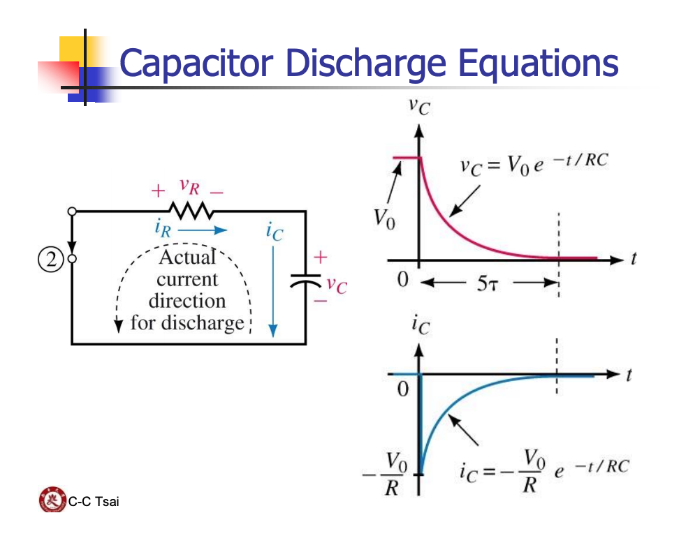
The voltage across the capacitor at any time after the dump is initiated is given by:
where is the initial voltage and is the time constant of the circuit. The design of a dump system revolves around choosing the appropriate resistance to meet specific safety and engineering requirements.
2. Designing a Dump Resistor: Step-by-Step
Designing a dump resistor isn't as simple as just picking a value for R. We must ensure the resistor can survive the immense energy dump without catastrophic failure. The process involves three key steps.
Step 1: Calculate the Required Resistance for a Target Discharge Time
The primary safety requirement is to reduce the bank voltage to a safe level within a specified time. The NFPA 70E standard, for instance, often cites 50V as a safe-touch threshold.
We can rearrange the discharge equation to solve for the resistance needed to achieve a target voltage in a time :
Let's look at a practical example from a specification document for a capacitor bank module.
Specification for the External Field Bank Module ...
This specification for a bank module at PPPL provides concrete examples of dump system design parameters. We'll examine the requirements for both the main dump resistor and a secondary 'bleed' resistor.
Please read Section 1.8, 'Dump' (page 9). Focus on the material choice, the stated safety target (discharge time and voltage), and the operational considerations like temperature monitoring.
The document specifies that the dump resistor must discharge the bank to below 50V within 30 seconds. This time is chosen based on how long it would take an operator to access the bank area after an emergency stop. The module consists of eight 55,650 µF capacitors charged to 1.4 kV.
- Total Capacitance
- Initial Voltage
- Safe Voltage
- Discharge Time
Using our formula:
This calculation gives us the target resistance value.
Step 2: Ensure Thermal Capacity
The resistor must absorb the bank's entire stored energy without melting, boiling, or otherwise failing. The total energy is:
This energy is converted into heat, , causing a temperature rise . Assuming the dump is fast enough to be considered adiabatic (no heat escapes during the dump), the temperature rise is:
where is the mass of the resistive material and is its specific heat capacity.
The following paper, though focused on modifying a crowbar circuit, provides an excellent, detailed design calculation for a high-energy stainless steel resistor package.
Effect Of Resistance Modification On EML Capacitor Bank ...
This paper from the Naval Research Laboratory details the design and testing of a resistor package for an electromagnetic launcher's power system. We will focus on the engineering calculations used to ensure the resistor's thermal and mechanical integrity.
Please read the section 'Resistor Package Design' on page 2 (PDF page 3). Pay close attention to Equation 2 (temperature rise) and Equation 3 (mechanical pressure), and how the calculated values are compared against material limits.
As you saw, the designers calculated a temperature rise of 89°C for a 350 kJ energy dump. They then explicitly state this is "well below the maximum temperature of the G-10 material [the insulator], which is 140 °C." This is a critical design check. The resistor must not only survive itself, but it must not damage any surrounding components.
Step 3: Assess Mechanical Stresses
Your work on magnet forces will make this concept familiar. High currents flowing through the dump resistor's conductors generate strong magnetic fields, resulting in significant Lorentz forces. If the resistor is made of parallel plates or wires, these forces will be mutually repulsive.
The NRL paper provides a formula to estimate the pressure between two parallel conductors:
where is the peak current and is the conductor width. The peak current during a dump occurs at : . The designers calculated this pressure, found the total force over the conductor area, and confirmed that the bolts holding the assembly together were strong enough, with a safety factor of two. This demonstrates that for high-energy systems, even the "passive" components require rigorous mechanical analysis.
Test your understanding!
You need to design a dump resistor for a 500 kJ, 20 kV capacitor bank with a total capacitance of 2.5 mF. The safety protocol requires the bank to be discharged to 100 V in 60 seconds.
- What is the required resistance ?
- If you build the resistor from 50 kg of stainless steel (), what is the expected temperature rise? Is this likely acceptable?
Show answer
-
Calculate Resistance:
-
Calculate Temperature Rise:
The total energy to dissipate is given as .
A temperature rise of only 20 K (or 20°C) is very modest and would be easily manageable, suggesting that 50 kg of steel provides a very comfortable thermal mass for this energy level.
3. Dump System Technologies and Topologies
Dump systems are implemented using various technologies and in slightly different ways, often with multiple layers of safety.
Main Dump Resistors
These are designed for the fast, active discharge we've been discussing. The two common types are:
- Solid-State Resistors: Often made of stainless steel plates or wires, chosen for high resistivity and durability. The NRL paper (LINK) is a perfect example of this type. They are robust but can have a large physical footprint to provide sufficient mass and surface area for cooling.
- Aqueous Resistors: These use an electrolyte solution (e.g., copper sulfate in water) as the resistive medium. The PPPL specification (LINK) describes this type. The primary advantage is the extremely high specific heat capacity of water, allowing them to absorb massive amounts of energy with a moderate temperature rise. The resistance can also be easily "tuned" by adjusting the electrolyte concentration.
Passive Bleed Resistors
In addition to the main dump system, capacitor banks are almost always fitted with bleed resistors.
Specification for the External Field Bank Module ...
Let's revisit the PPPL specification to understand the role of bleed resistors.
Now, read Section 1.3, specifically the final paragraph on page 6. Note the difference in purpose and discharge time compared to the main dump resistor.
As the document states, bleed resistors are a "passive 'last resort' safing mechanism."
- Purpose: To slowly drain the bank if the main dump system fails completely.
- Resistance: They have a very high resistance to ensure the discharge is slow (e.g., <50V over 12 hours in the example). This results in a much lower peak current and power dissipation. For the PPPL example, a 12-hour dump time would require a resistance of about 29 kΩ, compared to the ~20 Ω for the main dump.
- Connection: They are permanently wired in parallel with each capacitor. They are always working, continuously draining a tiny amount of charge.
4. Control and Activation: Fail-Safe Design
A safety system is only as good as its control logic. Dump systems are universally designed to be fail-safe. This is achieved using normally-closed (NC) switches or relays.
- An NC relay requires power to be held in the open position, disconnecting the dump resistor.
- During normal charging and operation, the control system energizes the dump relay to keep it open.
- If there is a loss of control power, a fault is detected, or an emergency stop is triggered, the power to the relay is cut. The relay then mechanically reverts to its default closed state, connecting the resistor and dumping the bank's energy.
This ensures that any failure in the control system itself results in the system defaulting to a safe state.
Specification for the External Field Bank Module ...
To see how this fail-safe logic is implemented, we will look at the connection schematics in the PPPL document.
Please review Section 1.14 'Connections' and Figure 10 on page 11. Also, look back at the main schematic in Figure 1 on page 4. Observe how the dump relay is shown as normally-closed and how E-stops and Kirk Keys control its power.
The system is typically activated by several triggers:
- Emergency Stop (E-Stop) Buttons: Located in the control room and near the magnet, these immediately cut power to the dump relays.
- Safety Interlocks: Switches on the magnet enclosure doors, cooling water flow sensors, etc. If an interlock is broken, the dump is triggered.
- Kirk Key Systems: A procedural safety system using physical keys to enforce a safe sequence of operations, ensuring the bank is dumped before personnel can enter a hazardous area.
- Software Control: For routine end-of-day shutdown or aborted shots.
Conclusion
Today we've covered the essential principles and practices for designing a critical safety component in any pulsed power system. You are now equipped to perform the first-order design calculations for a system that safely dissipates the enormous energy stored in a high-field magnet's capacitor bank.
Key Takeaways:
- A dump system is a engineered RC circuit designed to safely dissipate the capacitor bank's stored energy as heat in the event of a fault or for procedural shutdown.
- The design process involves calculating the required resistance for a target discharge time, verifying the resistor's thermal capacity to absorb the total energy (), and assessing mechanical forces.
- Two distinct systems are often used: a fast, active main dump resistor (solid-state or aqueous) and a slow, passive bleed resistor for redundant, last-resort safety.
- Control systems for dump resistors are designed to be fail-safe, typically using normally-closed relays that engage the dump upon any loss of power or trigger from an E-stop or interlock.
Next Lesson Preview:
Now that we've covered the core power electronics for generating a single pulse and ensuring safety, we will move on to more advanced techniques. In the next lesson, we will see how multiple capacitor bank modules can be fired with precise timing to create longer, shaped current pulses, which are essential for many modern high-field experiments. This involves analyzing multi-stage capacitor discharge systems with sequential triggering to generate complex pulse shapes.