Hello! Welcome to the fifth lesson in our module on pulsed field generation.
In our last lesson, we explored the high-power switches—thyristors and ignitrons—that act as the gatekeepers for the capacitor bank's energy. We established that these are not ideal switches; they have a small voltage drop when conducting and take a finite time to turn on. This non-ideality is not just a minor imperfection; it has significant consequences for the magnet's performance.
Today, we will address the learning outcome: Estimate switching and conduction losses in the power system and assess their impact on achievable peak field. We will move from the ideal RLC circuit model to a more realistic one that accounts for energy dissipation. Understanding where the energy goes is fundamental to designing an efficient system and predicting its ultimate performance limits.
1. Ideal vs. Real Switches: The Origin of Losses
An ideal switch would have zero resistance when 'on' and infinite resistance when 'off', transitioning between these states instantaneously. In this perfect world, no energy would be lost in the switch itself. However, as we've learned, real devices are more complex. This leads to two primary categories of energy loss in the power electronics:
- Conduction Loss: Occurs when the switch is in its 'on' state, conducting the main current. Due to a non-zero on-state resistance () or a forward voltage drop (), power is dissipated as heat ( or ).
- Switching Loss: Occurs during the finite time interval when the switch transitions from 'off' to 'on' (or vice versa). During this brief period, there is simultaneously a significant voltage across the switch and current flowing through it, resulting in a momentary, but often large, pulse of power dissipation.
To build a solid foundation for these concepts, please watch the following video from MIT OpenCourseWare. It provides a clear, general introduction to both loss mechanisms.
Lecture 15: Switching Losses and Snubbers
This video lecture introduces the concepts of conduction and switching losses by comparing ideal and practical switches. It then derives the expressions for calculating both types of loss.
Please watch the following three segments: The introduction from 00:00 to 02:49, which defines the two main types of losses. The explanation of conduction loss from 04:16 to 06:23, which shows how to calculate it for different devices. The derivation of switching loss from 06:23 to 12:41, which illustrates the V-I overlap during transitions.
2. Quantifying Conduction Losses in a Pulsed Magnet Circuit
As the video explained, conduction loss is the power dissipated while the circuit is conducting current. In our pulsed magnet system, several components contribute to this. Let's analyze them using the power supply design from a paper by Wu et al. as a practical example.

The total energy dissipated due to conduction during the current rise (the first quarter-period, ) is the sum of the energy lost in each resistive element:
Here, is the forward voltage drop across the thyristor (typically 1-3 V). We also have losses in the crowbar diode during the pulse decay, and resistive losses in the busbars and capacitor bank's equivalent series resistance (ESR).
The most significant contributor is typically the resistance of the magnet coil itself. Your background in electromagnetism will make the calculation of this Joule heating familiar.
A great example of how these losses are incorporated into system design calculations can be found in the following paper.
A Versatile DC/Pulse Switching Mode Power Supply for an ...
This paper describes the design of a power supply for an electromagnet. We will focus on the section where the designers calculate the required capacitor voltage, explicitly accounting for energy losses.
First, briefly review Section 2 and Figure 1 (page 1) to understand the circuit's operating stages. Then, focus your attention on Section 3.2, 'Capacitor Operating Voltage' (page 2), particularly Equation (4). This equation represents the core energy balance of the system.
Let's dissect Equation (4) from the paper, which expresses the energy balance for the discharge phase:
Here, is the initial capacitor voltage, and is the peak magnet current. The term relates to the voltage maintained during a flattop, which we can ignore for a simple sinusoidal pulse. The "Losses" term is what we're interested in. The paper approximates the total energy dissipated during the current rise ( to ) as:
(Note: The paper uses an IGBT switch, which functions similarly to our thyristor, with a forward voltage drop ).
This is derived by integrating the instantaneous power over the first quarter-cycle of a sine wave, where and . The first term is and the second is . These equations allow us to make a direct, physics-based estimate of the energy dissipated as heat in the main components.
3. Quantifying Switching Losses
As the MIT video detailed, switching losses occur due to the V-I overlap during turn-on and turn-off. For our main thyristor switch firing into the magnet coil, the turn-on process is the dominant source of switching loss.
The energy lost in a single turn-on event () can be estimated by modeling the voltage and current as linear ramps during the transition time, . This results in a triangular power profile. The total energy lost is the area under that triangle:
Where is the initial capacitor voltage , is the peak current the circuit would have reached, and is the rise time of the current through the switch.
In a high-power pulsed magnet system, is very short (microseconds), but and are very large (tens of kV and tens of kA), so this energy loss can be substantial. This dissipated energy is highly concentrated in the silicon wafer of the thyristor, which is why the dI/dt rating we discussed in the last lesson is so critical. Exceeding it causes extreme localized heating that destroys the device.
4. A Deeper Look: Losses in Magnetic Components
Beyond the switch and coil, other components can contribute losses. If a magnetic switch (saturable inductor) is used, as discussed previously, it will have "iron losses" in its core material. Similarly, any iron yokes or structural steel near the coil can experience losses. A detailed analysis, common in advanced FEM modeling, breaks these down further.
Optimisation and Loss Analyses of Pulsed Field ...
This recent research paper on pulsed field magnetization provides a sophisticated analysis of copper and iron losses. It's an excellent example of how these concepts are applied in cutting-edge design and modeling.
Please read the following sections: Section 3.2.1 'Iron loss model' (page 5), to see the Bertotti equation, which separates losses into hysteresis, eddy current, and excess loss components. Section 4.2 'Copper loss' (page 12), which shows calculated results for conduction losses in windings. Section 4.3.3 'Discussion on the iron loss' (page 16), which compares the magnitudes of the different iron loss components.
As you saw, the Bertotti equation provides a powerful framework:
This separates the total iron loss () into:
- Hysteresis loss: Energy lost tracing the B-H loop. Proportional to frequency ().
- Eddy current loss: From currents induced in the conductive core. Proportional to .
- Excess loss: An empirical term for other dynamic effects.
For our single pulse, the "frequency" is represented by the spectrum of Fourier components that make up the pulse shape. This level of analysis is crucial for precision modeling, especially in systems with significant magnetic materials, and is something you might encounter in software like PMDS or COMSOL Multiphysics.
5. The Bottom Line: Impact on Peak Field
Now, we tie everything together. Every joule of energy dissipated as heat is a joule that is not converted into magnetic field energy.
The initial energy stored in the capacitor bank is .
The peak energy stored in the magnet's field is .
In an ideal, lossless circuit, . In a real circuit, the energy balance is:
where is the sum of all conduction, switching, and iron losses over the pulse duration.
Solving for the peak current, we get:
This equation is the critical takeaway. It explicitly shows how energy losses directly reduce the achievable peak current. Since the magnetic field is proportional to the current (), any loss directly lowers the maximum field you can generate with a given power supply.
For example, if the total losses () amount to 10% of the initial capacitor energy, the peak magnetic energy will only be 90% of the initial energy. This means the peak current (and field) will be reduced by a factor of , a 5% reduction in peak field. In a system pushing the limits of technology, a 5% loss is enormous.
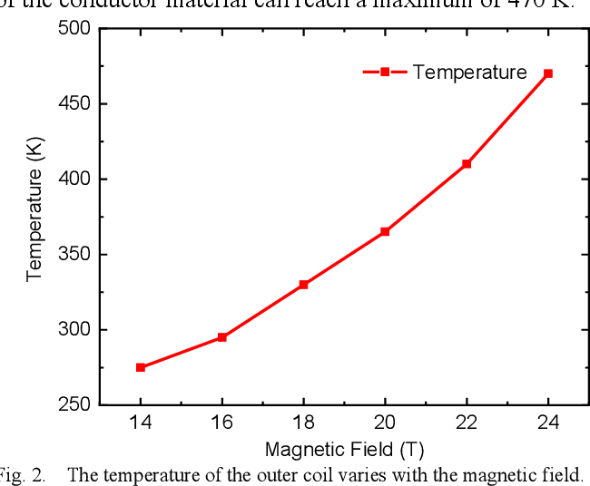
The heat generated by these losses also raises the temperature of the coil, which in turn increases its resistance (), further increasing conduction losses on subsequent pulses. This positive feedback loop is a key factor limiting the repetition rate of a pulsed magnet.
Test your understanding!
A pulsed magnet system has a 10 mF capacitor bank charged to 10 kV. The magnet coil has an inductance of 5 mH and a resistance of 10 mΩ. Assume the main switch has a constant forward voltage drop of 3 V. Using the formulas for energy loss during the current rise, estimate the total conduction loss and the percentage reduction in peak field compared to an ideal, lossless case.
Hint: First calculate the ideal peak current and the resonant frequency . Then calculate the energy loss in the coil and the switch over the first quarter period ().
Show answer
-
Initial Energy & Ideal Peak Current:
- Initial capacitor energy: .
- In an ideal circuit, .
- Resonant frequency: .
-
Calculate Conduction Losses (during rise time):
- Let's use the formulas derived from the integral over a sine wave from 0 to T/4, with .
- Coil Loss: .
- Switch Loss: .
- Total Conduction Loss: .
-
Impact on Peak Field:
- Energy available for the magnetic field: .
- Actual peak current: .
- Percentage reduction in current (and field): .
This simple calculation shows that even with a relatively low resistance, the conduction losses are not negligible and result in a measurable decrease in performance.
Conclusion
Today, we have moved beyond ideal circuit theory to confront the reality of energy loss in high-power systems. This is a critical step in understanding the practical limits of magnet design.
Key Takeaways:
- Real power systems have two main loss mechanisms: conduction loss (from resistance and voltage drops when current is flowing) and switching loss (from V-I overlap during turn-on/off).
- Conduction loss in the magnet coil () is often the largest single source of energy dissipation in a pulsed magnet.
- We can create an energy balance equation () to explicitly calculate how these losses reduce the energy available for the magnetic field.
- This reduction in available energy directly lowers the achievable peak field for a given capacitor bank voltage, impacting the ultimate performance of the magnet.
Next Lesson Preview:
We have now quantified the energy lost and seen its effect on the peak field. This naturally leads to the concept of efficiency. In our next lesson, we will formalize this by learning how to apply energy conservation to relate input electrical energy, stored magnetic energy, and dissipated heat to determine system efficiency. This will give us a key figure of merit for comparing different magnet designs.