Hello! Welcome back to our course on high-field magnet design.
In our last lesson, we explored how to generate complex pulse shapes by sequentially triggering multiple capacitor banks. While effective, these methods often dissipate the enormous energy stored in the magnetic field as heat after the pulse. Today, we'll address a more elegant and efficient approach, directly tackling the learning outcome: Describe energy recovery systems that recapture magnetic field energy to improve efficiency and repetition rate.
We will investigate why recovering energy is so critical and explore the circuits and strategies used to capture the energy from the collapsing magnetic field and store it for the next pulse. This not only saves power but, more importantly, drastically reduces the thermal load on the coil, which is often the main bottleneck limiting how frequently a magnet can be pulsed.
1. The Motivation for Energy Recovery
When a pulsed magnet is fired, a huge amount of electrical energy is converted into magnetic field energy, stored in the volume of the coil, given by . At the end of the pulse, this energy must go somewhere. In a simple crowbarred circuit, it is converted entirely into heat () in the coil and crowbar resistor. This heating is a major problem:
- Inefficiency: It represents a massive waste of energy, increasing operational costs.
- Low Repetition Rate: The coil must cool down before it can be pulsed again, a process that can take many minutes. This severely limits the data acquisition rate for experiments.
Energy recovery systems aim to solve this by capturing a large fraction of the magnetic field energy and returning it to the power supply. The impact is significant, as illustrated in the figure below.
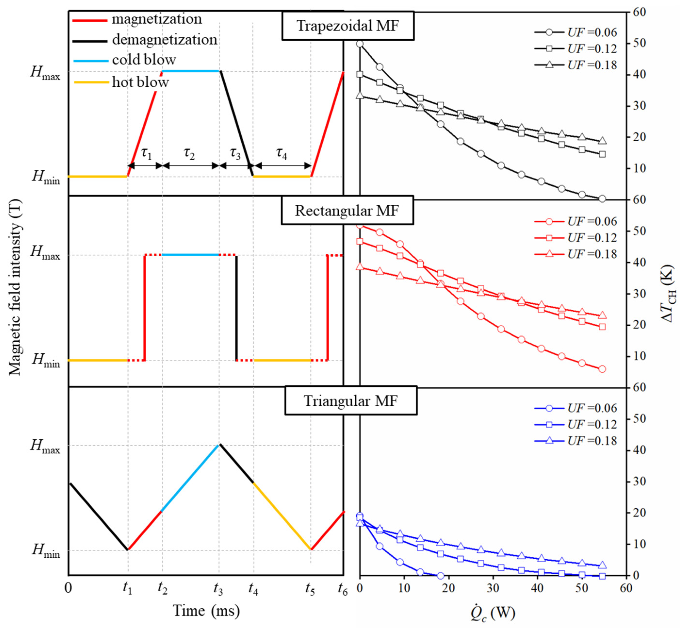
As you can see, for any given pulse shape and cooling power, a higher utilization factor (i.e., better energy recovery) results in a smaller temperature rise (). This direct link between energy recovery and thermal management is the primary driver for its use in all modern, high-repetition-rate pulsed field facilities.
2. The Principle: Redirecting the Flow of Energy
The core idea of energy recovery is to actively manage the current during the decay phase of the pulse. Instead of letting the current circulate through a simple resistive path (like a crowbar diode), we use a set of high-power switches to redirect it, forcing it to recharge a capacitor.

The circuit in Figure 2 illustrates this concept. The "Magnetic Energy Recovery Current Switch" is placed between the power source and the inductive load (the magnet). During the field ramp-down, the switches are configured to channel the current from the magnet into the capacitor C, storing the energy as . This stored energy can then be used for the next pulse, dramatically improving efficiency.
Let's look at a few specific topologies.
3. A Simple Implementation: The Bernardes & Merryman Circuit
One of the conceptually simplest energy recovery circuits is the Bernardes & Merryman (B&M) topology. It doesn't require complex control systems, relying instead on a resonant transfer of energy between two capacitor banks.
Design of a Low-Energy FARAD Thruster
The following document, although for a plasma thruster, provides an excellent description of the B&M circuit, a classic energy recovery topology.
Please read the subsection '2. Bernardes and Merryman Power Train', including its description of Figure 6. Focus on how the two capacitor banks interact through the drive coil and what happens to the energy at the end of the pulse.
As you've read, the B&M circuit operates as follows:
- Capacitor
C1is charged to the initial voltage , whileC2is at 0 V. - The switch is closed, and the LCR circuit formed by
C1,C2, and the magnetLbegins to oscillate. - Current flows from
C1through the magnet, building the magnetic field. This same current simultaneously chargesC2. - After the transient, the charge is distributed between
C1andC2. At least half of the energy remaining in the circuit is now stored inC2, effectively recovered. - A significant secondary benefit is that this topology prevents the large voltage reversal that a simple LCR discharge would cause on the primary capacitor, reducing stress and increasing its operational lifetime.
While simple and robust, the B&M circuit offers only partial energy recovery. For the highest performance, magnet facilities use more advanced, actively controlled systems.
4. Advanced Energy Recovery with Active Power Converters
Modern high-repetition-rate facilities, like those at CERN or LNCMI, use sophisticated power electronics to precisely manage the energy flow between the grid, a local energy storage element, and the magnet. A common architecture involves a boost converter and an H-bridge.
Study of Power Converter Topologies with Energy ...
The following technical report from CERN details the analysis of a modern power converter topology designed for energy recovery. This is a dense but highly relevant document that reflects the state-of-the-art.
Please read the introduction (Section 1) to understand the system's architecture. Pay close attention to Figure 1 and the role of each stage: the diode rectifier, boost converter, H-bridge, and the energy storage capacitor Cdc.
This topology is powerful because it decouples the magnet from the grid.
- The H-bridge directly drives the magnet. It's a "4-quadrant" converter, meaning it can apply positive or negative voltage to the magnet, driving current in either direction. This is key: applying a positive voltage ramps the field up (delivering energy), while applying a negative voltage during ramp-down allows it to act like a generator, extracting energy from the field.
- The Energy Storage Capacitor (
Cdc) is the crucial intermediary. It's a large local capacitor bank that acts as a buffer. It provides the instantaneous power for the pulse and, more importantly, it's where the H-bridge "dumps" the recovered energy during ramp-down. - The Boost Converter manages the energy flow between the grid and
Cdc. Its job is to keepCdccharged, drawing power from the grid in a controlled way to avoid disruptive power spikes.
With this architecture, the system can implement sophisticated control strategies to manage the energy recovery process.
Study of Power Converter Topologies with Energy ...
Now let's examine the control strategies that govern this energy transfer. The CERN paper describes two main approaches.
Skim through sections 4.1 ('Energy Balance equation') and 4.2 ('Control Strategies for Grid Peak Power Limitation') to grasp the core ideas. Don't worry about the detailed control loop equations. Focus on the conceptual difference: Energy Balance (EB): How does it separate the handling of active (dissipative) and reactive (stored) power? Limited Input Power: How does this simpler strategy work by just putting a cap on the power drawn from the grid? Finally, read section 7.3 ('Control strategies') for a clear summary comparing these approaches.
Let's summarize the key ideas from that reading.
-
Energy Balance (EB) Strategy: This is the most efficient approach. The system uses knowledge of the magnet's current and inductance to calculate the instantaneous active power (losses, ) and reactive power (energy storage, ). The control loop then tasks the power grid with supplying only the active power needed to cover losses, while the local capacitor
Cdcis responsible for providing and re-absorbing all the reactive power. This results in the smoothest possible draw from the main electrical grid. -
Limited Input Power Strategy: This is a more robust, simpler strategy used when the magnet parameters might not be known precisely. Instead of a complex energy balance calculation, the system simply enforces a hard limit on the current drawn from the grid (
ILmax).- When the magnet demands more power than this limit, the extra is drawn from
Cdc, causing its voltage to drop. - When the magnet's field collapses and returns energy, it recharges
Cdc. If the voltage onCdcrises above its target, the boost converter simply stops drawing power from the grid.
This effectively usesCdcas an overflow and buffer tank, ensuring the grid never sees a power demand greater than the prescribed limit.
- When the magnet demands more power than this limit, the extra is drawn from
Test your understanding!
Imagine you are running a pulsed magnet facility connected to a grid that is sensitive to large, sudden changes in power draw. Which of the two control strategies described—Energy Balance (EB) or Limited Input Power—would be more suitable, and why?
Show answer
The Energy Balance (EB) strategy would be more suitable. Its entire purpose is to smooth the load on the electrical grid. By tasking the grid with supplying only the relatively small and slowly-varying active power (dissipative losses), while the local storage capacitor handles the massive, rapid exchange of reactive power, the EB strategy minimizes the peak power and fluctuations seen by the grid. The Limited Input Power strategy also constrains the grid power, but in a less smooth, on/off manner that could still be disruptive.
Conclusion
In this lesson, we have moved beyond simply dissipating magnetic energy and explored the critical technology of energy recovery. This is not just a matter of "green" engineering; it is an enabling technology that directly determines the performance, particularly the repetition rate, of modern pulsed field magnets.
Key Takeaways:
- Energy recovery systems are essential for improving the efficiency and increasing the repetition rate of pulsed magnets by minimizing the thermal load on the coil.
- The fundamental principle is to use active electronic switches to redirect the current from the collapsing magnetic field back into a storage capacitor.
- Simple topologies like the Bernardes & Merryman circuit offer partial, passive energy recovery and prevent capacitor voltage reversal.
- Advanced systems use a multi-stage power converter (e.g., boost converter + H-bridge) with a large local storage capacitor (
Cdc) to actively manage energy flow. - Sophisticated control strategies, such as Energy Balance or Limited Input Power, allow these systems to optimize for grid stability and overall efficiency.
Next Lesson Preview:
Having now covered the full electrical circuit from the power source and capacitor banks to pulse shaping and energy recovery, we have a complete picture of the pulsed power system. In our next lesson, we will shift our focus from the electrical domain to the mechanical one. We will begin the critical process of designing the coil itself, starting with the fundamental analytical formulas used to determine the geometry needed to produce a target magnetic field.