Hello! Welcome to your fifth lesson in the "Principles of Pulsed Field Generation" module.
In our previous lesson, we established a crucial link between the electrical current pulse and its thermal consequences. We saw how to estimate the adiabatic temperature rise in a conductor by equating the "action integral," which characterizes the pulse, with the "material integral," which describes the conductor's thermophysical properties. We now have a clear understanding of two key energy figures: the maximum magnetic energy stored in the coil (), and the energy dissipated as heat ().
Today, we will unite these concepts under the principle of energy conservation. Our goal is to apply energy conservation to relate the input electrical energy, stored magnetic energy, and dissipated heat to determine system efficiency. We will create a complete energy budget for a single pulse, tracing the energy from its source—the capacitor bank—to its ultimate destinations. Understanding this energy balance is fundamental to designing magnets that are not only powerful but also efficient and durable.
1. The Energy Budget of a Pulse
The generation of a magnetic field pulse is fundamentally an energy conversion process. The entire sequence is governed by the energy stored in a capacitor bank. Let's trace this energy through the circuit.
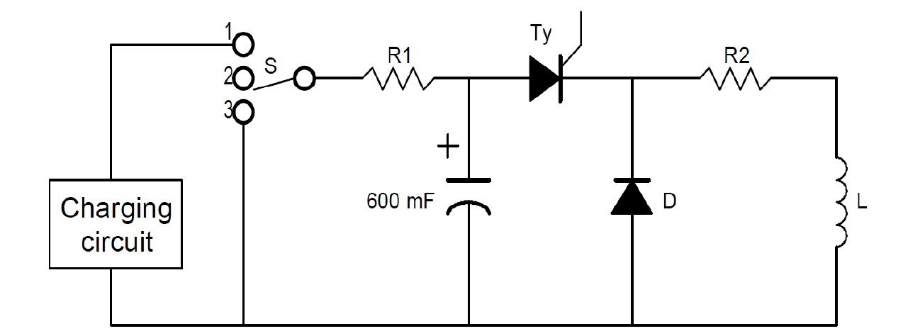
The energy journey can be broken down into three main components:
1. Input Electrical Energy ()
The process begins with the capacitor bank charged to an initial voltage . This is the total energy reservoir for the pulse.
2. Useful Stored Magnetic Energy ()
The primary objective is to convert the electrical energy into magnetic energy stored in the coil's volume. This energy reaches its maximum at the moment of peak current, .
This stored energy is what performs the "work" of the magnet, i.e., subjecting a sample to a high magnetic field.
3. Dissipated Energy ()
According to the first law of thermodynamics, energy cannot be created or destroyed. Any energy from the capacitor that is not stored in the magnetic field at peak current must have been converted into another form. In our RLC circuit, this conversion is overwhelmingly due to Joule heating in the resistive components. Therefore, the energy budget is:
Here, is the heat dissipated during the current rise to its peak. Over the full pulse cycle (rise and fall), all the initial energy is eventually dissipated as heat (in a standard RLC circuit). However, the partitioning of energy at the moment of peak field is what defines the system's effectiveness.
The total dissipated heat over the entire pulse is given by the integral of the instantaneous power loss:
where includes the resistance of the coil windings, switches, and connecting busbars. As we saw last lesson, this resistance is temperature-dependent.
2. Defining and Calculating System Efficiency
A critical figure of merit for a pulsed magnet system is its energy transfer efficiency, . It tells us how effectively we convert the initial stored electrical energy into the desired peak magnetic energy.
This metric directly reflects the quality of the magnet and power system design. An efficiency of 100% would mean zero resistive losses (), which is physically impossible for a non-superconducting magnet.
Let's ground this in a practical example from a real-world high-field magnet design.
Design of a Large-Bore 60-T Pulse Magnet for Sandia ...
To see how these energy components are balanced in practice, let's examine the design parameters for a magnet system developed at the National High Magnetic Field Laboratory (NHMFL).
Please review Table I, which lists the main parameters for two coils. Focus on the specifications for 'Coil #1'. Take note of the 'Capacitance energy', 'Coil inductance', and 'Peak current'.
Using the values for Coil #1 from the table, we can calculate its efficiency:
- Input Energy (): The capacitor bank stores .
- Peak Stored Magnetic Energy (): The coil has an inductance and reaches a peak current .
- Efficiency ():
This tells us that for Coil #1, over 76% of the energy from the capacitor bank is successfully converted into magnetic field energy at the peak of the pulse. The remaining , or approximately , has been dissipated as heat during the current's rise. This enormous amount of heat (enough to boil about a liter of water) is absorbed by the coil, causing the temperature rise we studied in the last lesson. The connection is direct: the energy lost, , is precisely the heat that drives up the temperature.
3. Factors Influencing Efficiency
What determines whether the efficiency is 65% or 80%? The efficiency of an underdamped RLC circuit is fundamentally governed by its quality factor, .
A high Q-factor signifies low damping, meaning energy sloshes between the capacitor and inductor for many cycles. A low Q-factor means energy is rapidly dissipated by the resistor. For the first quarter-cycle of our pulsed magnet, the energy transfer efficiency can be shown to be approximately:
This key relationship reveals the factors that engineers must optimize:
- Resistance (): Efficiency is exponentially sensitive to the total circuit resistance. This is the primary lever for improvement. Minimizing by using highly conductive materials (like OFHC copper), robust connections, and low-loss switches is paramount.
- Temperature: As we know, resistance is not constant; it increases with temperature (). This means efficiency is also temperature-dependent.

This is why pulsed magnets are almost always pre-cooled with liquid nitrogen (77 K). Starting with a lower initial resistance leads to a higher and better efficiency for the first pulse. It also provides a larger temperature margin before reaching the material's failure point.
Test your understanding!
Using the data from Table I in the "Design of a Large-Bore 60-T Pulse Magnet..." paper, calculate the energy transfer efficiency for Coil #2. How does it compare to Coil #1? What is the total energy dissipated as heat () in Coil #2 during the pulse?
Show answer
From Table I for Coil #2:
- Input Energy ():
- Inductance ():
- Peak Current ():
-
Calculate Peak Stored Magnetic Energy ():
-
Calculate Efficiency ():
This is significantly lower than the 76.5% efficiency of Coil #1. -
Calculate Dissipated Heat ():
An immense 1.39 MJ of energy is converted to heat within the coil during the pulse.
4. A Note on Efficiency in Inductive Energy Storage
While capacitor banks are the standard for facilities like LNCMI, it's insightful to know that energy can also be stored purely inductively (e.g., in a superconducting coil) and then rapidly discharged. The concept of efficiency is just as critical there, though the definitions change slightly.
Pulse Power Systems Employing Magnetic Energy Storage.
To broaden our perspective, let's briefly look at efficiency in inductive energy storage systems. This report analyzes the charging and discharging phases.
Please read the 'VII. CONCLUSIONS' section. Notice the discussion on the trade-offs in charging efficiency and, more importantly, the analysis of 'discharge efficiency'. The text states that the division of stored energy between the load and the switch results in efficiencies of 50-80%. This is analogous to our capacitor-to-magnet efficiency, where energy is divided between the magnet (load) and the circuit resistance (switch).
The key takeaway is universal: in any pulsed power system, a battle is waged between delivering energy to the load and losing it to resistance. The efficiency quantifies who wins.
Conclusion
In this lesson, we constructed a complete energy budget for a capacitor-driven pulsed magnet. By applying the principle of energy conservation, we were able to define, calculate, and analyze the system's energy transfer efficiency.
Key Takeaways:
- The energy from a capacitor bank () is partitioned between peak magnetic energy () and dissipated heat ().
- Energy transfer efficiency () is the ratio of peak magnetic energy to initial electrical energy, a primary figure of merit for a pulsed system.
- Efficiency is fundamentally limited by the circuit's Q-factor, making low resistance the most critical design goal.
- Because resistance increases with temperature, efficiency decreases as the coil heats up, highlighting the importance of pre-cooling.
Next Lesson Preview:
We have now established a comprehensive picture of the energy flow in a pulsed magnet system. We know how the stored energy relates to the peak field, how the circuit parameters define the pulse duration, how the dissipated energy heats the coil, and how all these factors combine to determine efficiency.
In the next lesson, we will synthesize this knowledge to understand the figures of merit for pulsed magnets. We will go beyond just peak field and look at a multi-faceted evaluation, comparing magnets based on peak field, pulse duration, field homogeneity, and available sample volume.