Hello! Welcome back to our course on high-field magnet design.
In our last lesson, we quantified the significant heat load that eddy currents from a magnet pulse deposit into a cryostat. We saw how this dynamic heating directly leads to cryogen boil-off, impacting operational costs and cryogenic capacity. This raises a critical question: how do we maintain a sample at a precise, stable temperature when the thermal environment is so hostile?
Today, we will answer that question by designing the "brain" and "muscles" of the sample environment: the temperature control system. Our learning outcome is to design a conceptual temperature control system for a Variable Temperature Insert (VTI), specifying thermometers, heaters, and PID logic. We will move from the basic principles of feedback control to the sophisticated, multi-layered strategies used in world-class facilities like the one you'll be working at.
This lesson will bridge the gap between abstract control theory and the practical art of managing millikelvin stability in the extreme environment of a high-field magnet.
1. The Core Components: Sensing and Acting
Any control system relies on three fundamental actions: sensing the state of the system, acting to change that state, and a control logic to decide what action to take. Let's begin with the physical hardware for sensing and acting.
1.1. Sensing: Cryogenic Thermometry in High Fields
To control temperature, you must first measure it accurately. This is uniquely challenging in our application.
A good starting point for understanding the available sensor technologies is the following thesis, which provides a concise overview.
Temperature Control of a High Vacuum Chamber
The document 'Temperature Control of a High Vacuum Chamber' by Ricardo Jorge Vilarinho Alves provides a clear comparison of common temperature sensors used in vacuum and cryogenic systems.
Please read section 4.4.1 'Temperature sensors' and the summary table in 4.4.1.1. Focus on the characteristics of Resistive Temperature Detectors (RTDs) and Thermocouples, the two most relevant types for our application.
For cryogenic applications, Resistive Temperature Detectors (RTDs) are very common. Instead of platinum (Pt100/Pt1000) which loses sensitivity at low temperatures, specialized semiconductor composite resistors like Cernox™ or Rox™ are often used. They offer high sensitivity in the 1-300 K range.
However, all resistive sensors share a major vulnerability in our context: magnetoresistance. Their electrical resistance depends not only on temperature but also on the magnetic field. A 50 T pulse would render a standard temperature reading completely meaningless.
So, how is this problem solved in practice? The answer is meticulous calibration.
Kiloampere, Variable-Temperature, Critical-Current ...
The paper 'Kiloampere, Variable-Temperature, Critical-Current...' from NIST provides a deep dive into how a real-world, high-precision system deals with thermometry in high magnetic fields.
Please read Section 2.2, 'Thermometry'. Pay close attention to their calibration protocol and Figure 9, which shows the apparent change in temperature (ΔT) due to magnetoresistance. This is a crucial practical detail.
As the NIST paper demonstrates, the solution is to characterize the magnetoresistance of each thermometer for a specific magnetic field and temperature range. The control software then stores this calibration data (like the curves in Fig. 9) in a lookup table. During an experiment, the software reads the raw resistance, measures the magnetic field, and calculates the true temperature by correcting for the magnetoresistive effect. This is a perfect example of a multi-physics problem solved with software.
1.2. Acting: Heaters
The "muscle" of the temperature control system is the heater. In a VTI, temperature is stabilized by balancing a constant flow of cooling power (from liquid helium or nitrogen) with a precisely controlled amount of heating.
- Type: Heaters are typically simple resistive elements. Non-inductively wound wire or thin-film foil heaters laminated in an insulator like Kapton are common choices to minimize their interaction with the magnet's changing field.
- Placement: The placement of heaters and thermometers is a critical design choice that dictates the stability and accuracy of the system. They are often mounted together on a copper block, which acts as a thermal reservoir to provide uniform temperature. This assembly is then placed in good thermal contact with the sample mount.
The image below shows a real-world example of a sample probe, illustrating the integration of these components.

2. The Control Logic: From Simple PI to Advanced Strategy
With a sensor and an actuator, we now need the "brain" to connect them. This is the control logic, which is almost universally a Proportional-Integral-Derivative (PID) controller or a simplified variant.
2.1. PID Control Fundamentals
A PID controller calculates the difference (or "error", ) between the desired temperature setpoint and the measured temperature. It then computes an output—the power to apply to the heater—based on three terms:
- Proportional (P): The output is proportional to the current error. A large error results in a large corrective action. This provides the primary response.
- Integral (I): The output is proportional to the accumulated error over time. This term drives the steady-state error to zero, correcting for small but persistent offsets.
- Derivative (D): The output is proportional to the rate of change of the error. This term anticipates future error and can dampen overshoot, leading to a faster settling time.
The total output is a weighted sum: .
For thermal systems, which have intrinsically slow dynamics, the derivative term (D) can be overly sensitive to sensor noise, leading to erratic heater output. Therefore, a Proportional-Integral (PI) controller is often sufficient and more robust.
Temperature Control of a High Vacuum Chamber
The same thesis we viewed earlier also provides a good, practical explanation of PID/PI controllers and the rationale for choosing PI for a thermal system.
Please read Section 6.3, 'Positive temperatures controller'. Focus on the block diagram in Figure 63 and the discussion in 6.3.2 that explains why a PI controller was selected.
2.2. Tuning a PI(D) Controller
The performance of the controller depends entirely on the gain values , , and . The process of finding the optimal values is called tuning. There are systematic methods, like the Ziegler-Nichols method, that provide a good starting point based on the system's open-loop response (how it behaves without a controller).
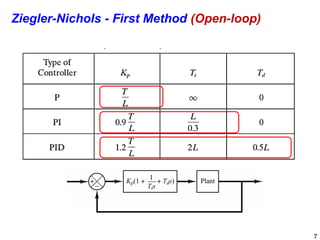
In practice, these initial values are almost always refined empirically ("by hand") to achieve the desired performance: fast response to setpoint changes with minimal overshoot and excellent stability against disturbances.
Test your understanding!
Imagine you have just turned on a PI controller to cool a sample from 10 K to 5 K. A magnet pulse occurs, dumping a burst of heat into the system and causing the temperature to spike to 5.5 K. Qualitatively describe how the Proportional and Integral terms of the PI controller will react to this disturbance.
Show answer
- Proportional (P) Term: The sudden temperature spike to 5.5 K creates a positive error (5.5 K - 5.0 K = +0.5 K). The P-term will react immediately and proportionally to this error, causing a sharp decrease in heater power to try and counteract the heat pulse.
- Integral (I) Term: As the temperature stays above the 5.0 K setpoint, the positive error begins to accumulate. The I-term will build up over time, also commanding a reduction in heater power. This term is crucial for ensuring that after the initial spike is handled by the P-term, the system doesn't settle at a temperature slightly above 5.0 K due to the residual heat. It ensures the system returns precisely to the setpoint.
3. An Advanced System Architecture: The NIST Multi-Loop Design
A single PI loop driving a heater is a good start, but high-performance systems require a more sophisticated strategy to handle the large dynamic range of temperatures and heat loads. The NIST system provides an excellent case study of a state-of-the-art design.
Kiloampere, Variable-Temperature, Critical-Current ...
Let's return to the NIST paper to see how they combine multiple control loops into a comprehensive system. This goes far beyond a simple PI controller.
Please read Section 2.1, 'Re-entrant Dewar and Control Loops', focusing on 2.1.1, 'Philosophy of Temperature Control in Gas'. Pay attention to the distinction between coarse and fine control loops and the role of the 'pre-regulator'.
The NIST design philosophy relies on a cascade of control loops:
-
Coarse Control (Loops #3 & #4): A pre-regulator intercepts the flow of cold helium gas coming from the main dewar. It has its own heater and thermometer (Loop #3). Its job is to pre-warm the gas to a temperature close to the final target temperature. The amount of gas flow is itself controlled by adjusting the pressure in the supply dewar (Loop #4). This is a crucial innovation: it buffers the sample from large fluctuations in the cooling power. Most of the heat generated by the high-current leads during a test is absorbed here, far from the sample.
-
Fine Control (Loops #1 & #2): Two separate heaters (H1 and H2) and thermometers (T1 and T2) are located at the top and bottom of the sample mount. These are the fine-tuning loops. They run at very low power (milliwatts) and are only responsible for making small, precise adjustments to bring the temperature of the pre-regulated gas to the exact setpoint.
This hierarchical or "cascade" design isolates the delicate task of fine temperature control from the "dirty" job of handling large, variable heat loads from the current leads and cryostat.
4. The Reality of Control: It's an Empirical Science
The final, and perhaps most important, lesson from the NIST paper is that even with this sophisticated design, achieving accurate temperature control is not a purely theoretical exercise. The system's behavior must be mapped empirically.
Kiloampere, Variable-Temperature, Critical-Current ...
The most fascinating part of the NIST paper is their verification process, which reveals a non-intuitive truth about temperature control: the act of controlling can interfere with the measurement.
Please read the introduction to Section 3, 'Verification of Variable Temperature Measurements', and skim Section 3.2. Focus on the discussion around Figure 26, 'Apparent temperature error ΔT versus the average heater power H2'.
The key finding, as shown in their Figure 26, is that the heater power itself introduces a systematic error. Higher heater power creates larger thermal gradients between the heater, thermometer, and sample. This can cause the sample to be "sub-cooled" relative to what the thermometer reads.
This leads to a profound conclusion:
- To get the correct temperature, you must operate the heater at a specific power level.
- This "correct" heater power level is not constant; it depends on the other heat loads in the system (e.g., self-heating from the sample).
- Therefore, the control "logic" is not just a PID algorithm. It is a complete control protocol, empirically determined, where the software targets a specific heater power as a function of the experimental conditions to minimize the temperature error.
This is the art and science of high-precision measurement: understanding and characterizing the limitations and subtle interactions of your own apparatus.
Conclusion
We have now designed a conceptual temperature control system for a VTI, moving from basic components to real-world complexities.
Key Takeaways:
- A VTI control system consists of thermometers (e.g., Cernox RTDs), heaters (e.g., resistive foils), and a control algorithm, typically PI logic.
- The primary challenge for thermometry in high fields is magnetoresistance, which must be corrected for using detailed, field-dependent calibration tables.
- High-performance systems employ a multi-loop or cascade strategy, using a pre-regulator for coarse control to buffer the fine control loop near the sample from large heat loads.
- Achieving millikelvin accuracy requires an empirically derived control protocol, not just a simple PID loop. The controller must actively manage thermal gradients by targeting specific heater power levels that are known to minimize measurement error under given conditions.
Next Lesson Preview
Having designed the thermal environment, we are now ready to place an experiment inside it. In our next lesson, we will tackle the challenge of performing sensitive electrical measurements in this noisy environment. We will design a system for resistivity or Hall effect measurements, addressing challenges like large inductive voltage pickup. This will take us into the heart of data acquisition in pulsed magnetic fields.