Hello! Welcome back to our course on high-field magnet design.
In our previous lesson, we explored the operational principles of Variable Temperature Inserts (VTIs), the systems responsible for creating a controlled thermal environment for experiments. We saw that a VTI's core function is to balance a continuous source of cooling power against a heater to maintain a precise sample temperature.
Today, we'll investigate a major challenge that the VTI and the entire cryogenic system must overcome in a pulsed magnet facility: parasitic heating. The very nature of a pulsed magnet—a rapidly changing magnetic field—is a perfect recipe for inducing currents in any nearby conductors. This lesson will focus on how to quantify this effect. Our learning outcome is to calculate the expected cryogen boil-off rate in a cryostat caused by eddy current heating during a magnetic field pulse.
This is a critical calculation in facility design, as it determines a significant operational cost (cryogen consumption) and places specific demands on the cooling capacity of the sample environment.
1. The Origin of Eddy Current Heating
A pulsed magnet generates a time-varying magnetic field, . While the field is strongest inside the coil bore, a significant stray field extends outwards, passing through the various components of the cryostat, such as the VTI tube, radiation shields, and vacuum chambers.
According to Faraday's Law of Induction, a changing magnetic flux, , through a conducting surface induces an electromotive force (EMF). This EMF drives currents within the conductive material of the cryostat walls. These swirling currents are known as eddy currents.
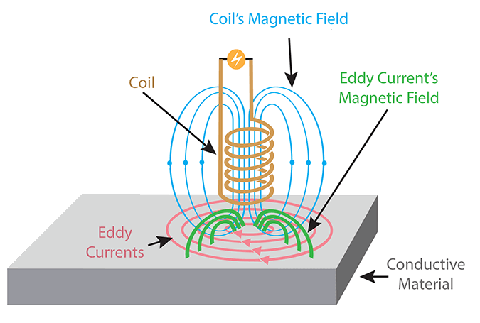
Since the metallic components of a cryostat have a finite electrical resistance, , these eddy currents dissipate power as heat according to Joule's law, . This dissipated power directly heats the cryostat components, and this heat must be removed by the liquid cryogens, causing them to boil off.
The magnitude of the induced EMF is proportional to . For the very fast rise and fall times of a high-field pulse, can be enormous (on the order of 1000 T/s or more), leading to substantial instantaneous heating.
2. A Rigorous Framework: Calculating Power Loss with Poynting's Theorem
While the conceptual picture is straightforward, calculating the exact eddy current paths and resulting power dissipation inside a complex geometry like a cryostat is challenging. A more elegant and powerful approach, well-suited to your physics background, is to use the Poynting theorem. This method is the foundation of how modern Finite Element Method (FEM) software solves this exact problem.
The Poynting vector, , represents the energy flux (power per unit area) of the electromagnetic field. The total power flowing into a closed volume is the integral of the Poynting vector over its surface. For an oscillating field, the time-averaged power dissipated as ohmic heat inside the volume is given by the real part of this surface integral.
A detailed derivation is provided in the following paper, which, despite its focus on MRI, presents the physics in a way that is directly applicable to our pulsed magnet scenario.
Minimization of eddy power loss in the cryostat for a z-gradient ...
The paper 'Minimization of eddy power loss in the cryostat...' by Takrimi and Atalar presents a robust method for calculating these losses using the Poynting theorem. This is the theoretical basis for numerical calculations in magnet design.
Please read Section 2.1, 'Poynting theorem and eddy power loss calculation'. Focus on Equation (1) and the four key points listed. This section establishes how you can calculate the total power dissipated within a volume (like a cryostat wall) by sampling the fields only on its surface.
As the paper explains, the time-averaged power loss for a sinusoidal field at frequency is:
where and are the phasor representations of the electric and magnetic fields on the surface , and is the complex conjugate of .
The key insight here is that you don't need to know the complex current distribution inside the conductor. If you can compute the tangential and fields on its surface, you can determine the total power being dissipated within it. This is a powerful computational technique.
3. Application to an Arbitrary Magnetic Pulse
A typical magnetic field pulse is not a simple sine wave; it's often a trapezoid, triangle, or half-sine shape. To apply the time-harmonic Poynting theorem, we must first decompose the pulse into its constituent frequencies using Fourier analysis.
Any periodic waveform with period can be expressed as a sum of sine and cosine waves (a Fourier series):
where is the fundamental frequency.
The total average power dissipated is then the sum of the powers dissipated by each individual frequency component. The following reading explains this superposition principle.
Minimization of eddy power loss in the cryostat for a z-gradient ...
To handle realistic pulse shapes, we combine the Poynting theorem with Fourier analysis. Each harmonic of the pulse contributes to the total heating, with higher frequencies often dominating.
Please read Section 2.3, 'Eddy power loss calculation for an arbitrary periodic excitation,' focusing on Equation (13). This shows how to sum the power contributions from each harmonic. Also, examine Section 3.1 and Figure 3, which vividly illustrate the strong frequency dependence of power loss. This is crucial: the sharp edges of a pulse contain high-frequency components that can contribute disproportionately to the heating.
The workflow for calculating the total power loss is therefore:
- Define the pulse shape and repetition rate .
- Compute the Fourier series of to find the amplitudes of its harmonics ().
- For each significant harmonic :
a. Use an FEM solver to compute the stray electric () and magnetic () fields on the surfaces of the cryostat components (e.g., the 77 K radiation shield, the 4.2 K bore tube).
b. Calculate the power dissipated by this harmonic, , using the Poynting theorem integral. - Sum the contributions: The total time-averaged power loss is .
This is precisely the kind of coupled electromagnetic calculation that software like PMDS is designed to perform.
4. From Power Loss to Cryogen Boil-Off
Once we have calculated the total average power (in Watts) being dissipated into a component, the final step is to determine how much cryogen this will boil off. The conversion is based on the latent heat of vaporization () of the cryogen.
For a power deposited into a liquid cryogen, the mass boil-off rate is:
The volumetric boil-off rate is:
where is the density of the liquid cryogen.
In practice, high-field laboratories use standard conversion factors for this calculation. The following resource provides the key number for liquid helium.
AC-loss considerations of a pulse SMES for an accelerator
The final step is a straightforward conversion from power to liquid consumption. The paper 'AC-loss considerations of a pulse SMES...' gives the standard conversion factor for liquid helium.
Please read the first paragraph of Section 2.1, 'Empirical method to define AC-losses'. Note the practical conversion factor provided for liquid helium at 4.2 K.
As stated in the paper, a power dissipation of 1 Watt at 4.2 K corresponds to a liquid helium boil-off of 1.378 liters per hour. This factor implicitly contains the latent heat and density of liquid helium. For other cryogens like liquid nitrogen, a similar factor can be calculated from its properties.
Example Calculation
Let's put it all together.
- A pulsed magnet generates a 50 ms pulse once every 5 minutes ( s).
- Using FEM analysis and the Fourier method described above, we find that the total energy deposited in the 4.2 K cryostat components per pulse is J.
- Step 1: Calculate the average power.
- Step 2: Convert average power to boil-off rate.
This is the additional boil-off caused by the magnet pulsing, on top of the cryostat's static heat leak. This calculation is essential for planning liquid helium deliveries and managing the operational budget of the facility.
Test your understanding!
A cryostat's aluminum radiation shield is held at 77 K by a liquid nitrogen (LN₂) bath. During repetitive pulsing, FEM simulations show a time-averaged power of 15 W is dissipated in the shield due to eddy currents.
Calculate the corresponding LN₂ boil-off rate in liters per hour.
Given:
- Latent heat of vaporization of LN₂: J/kg
- Density of LN₂: kg/m³
Show answer
First, let's calculate the boil-off rate in kg/hour.
Convert this to kg/hour:
Next, convert the mass rate to a volume rate using the density.
The eddy current heating will cause an additional 0.336 liters of liquid nitrogen to boil off every hour.
Conclusion
Today we have established a complete framework for calculating cryogen consumption due to eddy current heating from a pulsed magnetic field.
Key Takeaways:
- Rapidly changing magnetic fields induce eddy currents in the conductive walls of a cryostat, causing Joule heating.
- The power dissipated can be rigorously calculated by integrating the Poynting vector over the surface of the conductive components, a method well-suited for FEM simulations.
- For arbitrary pulse shapes, Fourier analysis allows us to sum the heating contributions from each frequency harmonic of the pulse.
- The total average power dissipated is converted into a volumetric boil-off rate using the cryogen's latent heat of vaporization and density. For liquid helium, 1 W of heating corresponds to 1.378 L/hr of boil-off.
This analysis shows that the design of the cryostat and the choice of pulse parameters have a direct and calculable impact on the operational cost and cryogenic demands of a high-field facility.
Next Lesson Preview
We have now explored the VTI's operating principles and analyzed a major dynamic heat load it must contend with. In our next lesson, we will shift focus to the "brain" that allows the VTI to maintain thermal stability in the face of such challenges. Our learning outcome will be to design a conceptual temperature control system for a VTI, specifying thermometers, heaters, and PID logic. We will delve into the practicalities of cryogenic thermometry in high magnetic fields and the art of tuning a control loop for fast, stable performance.