Hello! Welcome to the next lesson in our course on high magnetic field physics and construction.
Introduction
In our previous lesson, we investigated material fatigue, a failure mechanism driven by the repeated application of stress, even when that stress is below the material's ultimate strength. We saw how S-N curves and Miner's rule are used to predict the lifetime of a pulsed coil under cyclic loading.
Today, we shift our focus from the number of cycles to the magnitude and duration of stress. The forces within a high-field magnet can be so immense that they push materials beyond their elastic limit, causing permanent changes. This lesson directly addresses the learning outcome: Analyze plastic deformation and creep as failure mechanisms under sustained or repeated stress.
We will begin by defining plastic deformation and how it's quantified for the high-strength materials used in magnets. Then, we will delve into creep—a slow, time-dependent deformation that occurs under constant load. Critically, we will see how creep becomes a major concern in pre-loaded magnet structures, a common design feature in both pulsed and DC magnets. Finally, we'll examine a real-world case study of a failed high-field magnet to understand why accurately modeling plasticity is crucial for modern magnet design.
1. Plastic Deformation: The Point of No Return
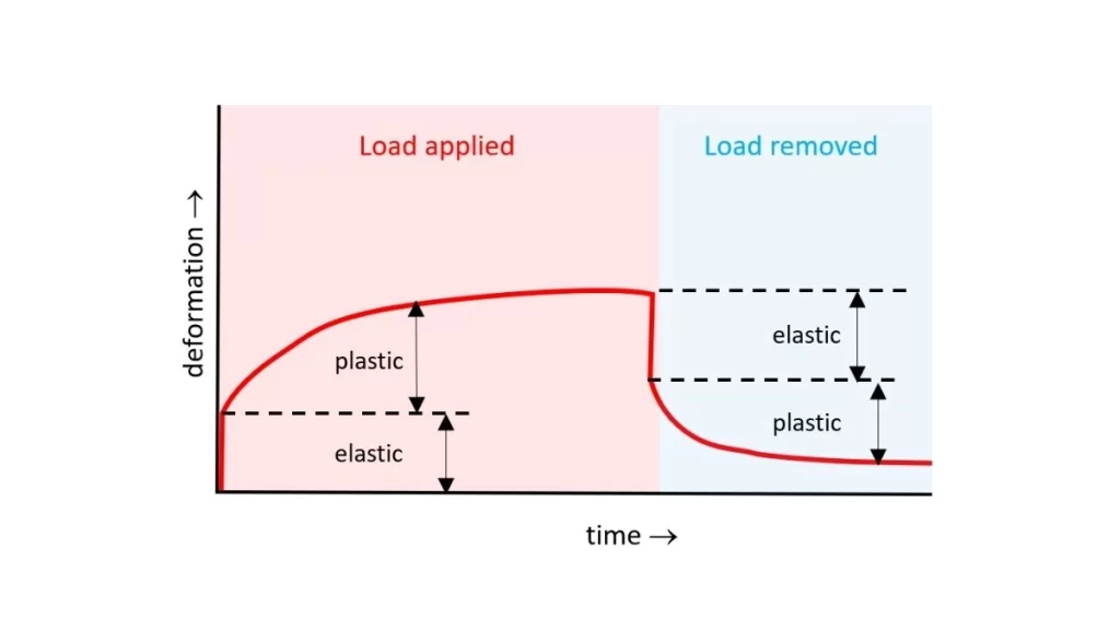
You'll recall from our earlier lessons on mechanics that when a material is stressed, it first deforms elastically, meaning it returns to its original shape when the load is removed. However, if the stress exceeds a certain threshold—the yield strength ()—the material undergoes plastic deformation, a permanent change in shape.
For many high-performance conductors and reinforcement materials, the transition from elastic to plastic behavior is gradual, without a sharply defined yield point on the stress-strain curve. In these cases, engineers use a practical convention called the 0.2% offset proof stress.

In the context of a pulsed magnet, exceeding the yield strength has direct consequences. A coil winding might permanently stretch, or a reinforcement layer might slightly deform. While a single instance might be non-catastrophic, this can lead to a loss of pre-compression, compromised insulation integrity, and altered cooling channel geometry, ultimately contributing to failure. This is precisely the phenomenon at the heart of the Low-Cycle Fatigue (LCF) regime we discussed previously, where plastic strain occurs with every cycle.
2. Creep: The Slow, Inexorable Deformation
While plastic deformation is an instantaneous response to overstress, creep is a time-dependent plastic deformation that occurs under a constant stress, even if that stress is below the material's nominal yield strength. It is often associated with high temperatures, but "high" is relative to the material's melting point (). For some materials, creep can be significant even at room temperature over long periods.
To understand the stages and temperature dependence of creep, please watch the following short video.
How materials can fail due to Creep
This video, 'How materials can fail due to Creep' from the Taylor Sparks channel, provides an excellent introduction to the stages of creep and the factors that influence it.
Please watch the video from the beginning to the timestamp 02:53. Focus on: The definition of creep as time-dependent plastic deformation. The three stages: primary, secondary (steady-state), and tertiary creep. The critical role of temperature and stress level in determining the creep rate.
As the video explains, the secondary or steady-state creep region, where the strain rate is constant, is the most important for predicting the long-term performance and lifetime of a component.
Microscopic Mechanisms of Creep
Your physics background provides the perfect foundation for understanding why creep happens. It's not magic; it's the result of thermally activated atomic and microstructural processes.
This video from the 'Introduction to Materials Science and Engineering' series delves into the physical mechanisms that enable creep.
Please watch the entire video. It provides a comprehensive overview of the four main creep mechanisms and how they relate to temperature and stress. Pay special attention to: Dislocation-based mechanisms: How cross-slip (for screw dislocations) and climb (for edge dislocations) allow dislocations to bypass obstacles, a process enabled by thermal energy. Diffusion-based mechanisms: How atoms migrate under stress, either through the bulk crystal (Nabarro-Herring creep) or along grain boundaries (Coble creep), leading to a change in grain shape. Grain boundary sliding: How grains can slide past each other at high temperatures. Deformation Mechanism Maps: The final segment introduces these maps, which are powerful tools for visualizing which deformation mechanism is dominant under different conditions of normalized stress (\sigma/E) and homologous temperature (T/T_m).
The steady-state creep rate () is often modeled using a semi-empirical Arrhenius-type relationship that captures the physics you just saw:
Where:
- is a material constant.
- is the applied stress.
- is the stress exponent. Its value gives clues about the dominant mechanism (e.g., for diffusional creep, for dislocation creep).
- is the activation energy for creep, which is often close to the activation energy for self-diffusion.
- is the gas constant and is the absolute temperature.
This equation powerfully summarizes that creep is a thermally activated process, driven by stress.
3. Creep and Plasticity in High-Field Magnet Systems
At first glance, creep might seem irrelevant for pulsed magnets with millisecond pulse durations. However, its importance becomes clear when we consider pre-loaded structures. To counteract the immense outward Lorentz forces during a pulse, many magnet designs incorporate a static pre-compression, often applied by external rings or presses. This preload is sustained for very long periods—months or years—creating ideal conditions for creep.
Let's examine a study on fusion tokamaks, which often use high-field resistive pulsed coils with significant preloads.
Creep Effects in the Toroidal Field Coils of Fire and Other ...
This report, 'Creep Effects in the Toroidal Field Coils of Fire and Other...', directly addresses the relevance of creep in pre-loaded pulsed systems.
Please read the following sections to understand how creep impacts magnet design: Abstract: Focus on the main conclusion about where creep comes from ('it is the preloads which introduce the most noticeable creep responses'). Section IV, first paragraph (starts 'Pulsed experiments typically...'): Read this paragraph to solidify your understanding of why long-duration preloads are more critical for creep than short, high-load pulses. Section VI, 'FIRE RESULTS': Skim this section to see a practical application. Note how the choice of material (OFHC copper vs. BeCu) drastically changes the creep response, and how creep in one part of the structure (the horizontal legs) affects another (the inner leg). Section VI, 'CONCLUSION' (top of p. 6): Read the summary of findings for the FIRE and IGNITOR designs.
The key insight from this paper is that long-term preloads, even at room or cryogenic temperatures, can cause significant creep strain. This can lead to a relaxation of the preload, meaning the carefully designed pre-compression is lost over time. This reduces the wedging pressure between coil segments and compromises the magnet's ability to withstand the operational out-of-plane forces, potentially leading to premature failure.
4. Case Study: Plasticity and Failure in a 95 T Magnet
Simple elastic material models are often insufficient to predict the behavior of state-of-the-art magnets, especially when they utilize advanced composite reinforcements. Let's look at a recent analysis of a failed magnet from the Wuhan National High Magnetic Field Center (WHMFC) to see why modeling plasticity is so critical.
Mechanical Behaviors of Polymer-Based Composite ...
This paper, 'Mechanical Behaviors of Polymer-Based Composite ...', is a deep dive into the failure of an ultra-high-field magnet. It highlights the shortcomings of traditional analysis.
Please read the following sections. You don't need to follow every equation, but focus on the conceptual story. Introduction (Section 1): Read the paragraphs starting with 'The unclear failure mechanism primarily arises...'. Note the criticism of using simple elastic models and the von Mises criterion, and the mention that Zylon fibers exhibit 'notable plastic behavior.' Conclusions (Section 7): Read the first paragraph. It summarizes the study's main point: a model incorporating plasticity and progressive damage was necessary to explain the failure. The failure cause was identified as local buckling, a result of stiffness attenuation that simpler models could not predict. Inner Magnet Analysis (Section 5.1): Skim this section and look at Figure 7 ('Stiffness attenuation...'). This shows the practical result of the advanced model: it predicts where the ZFRP reinforcement loses its stiffness due to micro-damage and plasticity, long before catastrophic failure. This is exactly the kind of detailed analysis your interest in FEM is suited for.
This case study is a powerful illustration of our lesson's topic. The failure of the 95 T prototype could not be explained by a model that ignored the plastic deformation and damage accumulation in the Zylon reinforcement. Only by developing a more sophisticated constitutive model could the researchers understand that the material was losing stiffness in critical areas, leading to buckling at a field well below the original design target. This underscores the necessity of accounting for plastic behavior in the design and simulation of extreme-field magnets.
Conclusion
Key Takeaways:
- Plastic deformation is a permanent change in shape that occurs when stress exceeds a material's yield strength, often defined by the 0.2% offset proof stress for high-strength alloys.
- Creep is a slow, continuous plastic deformation under a constant load, driven by thermally activated microscopic processes like dislocation motion and atomic diffusion.
- In high-field magnet systems, preloads applied for long durations are the primary driver of creep, which can lead to a dangerous relaxation of compressive forces.
- Accurately modeling plasticity and damage evolution is essential for understanding the failure mechanisms of modern magnets, especially those using complex composite reinforcements like ZFRP. Simple elastic models can be dangerously misleading.
Next Lesson Preview:
We have now explored mechanical failure from both cyclic loading (fatigue) and stress magnitude/duration (plasticity and creep). In our next lesson, we will turn our attention to a critical electro-thermal failure mode: thermal runaway. We will investigate how Joule heating can lead to a catastrophic, unstable increase in temperature and resistance, and what design strategies are used to prevent it.