Hello! Welcome to your next lesson.
Introduction
In our last lesson, we explored mechanical failure modes like plastic deformation and creep, which are driven by the magnitude and duration of stress. We saw how even carefully pre-loaded structures can fail over time.
Today, we pivot to a critical failure mechanism that bridges the electrical, thermal, and mechanical domains: thermal runaway. This lesson is designed to address the learning outcome: Describe the mechanism of thermal runaway in conductors and its prevention in magnet design.
We will start by dissecting the physics of thermal runaway—a positive feedback loop where Joule heating spirals out of control. We will then examine how this phenomenon manifests in real-world systems and, most importantly, explore the multi-faceted design strategies used to prevent it. This involves careful material selection, sophisticated thermal management, and intelligent geometric design, all concepts highly relevant to the state-of-the-art magnets at LNCMI.
1. The Physics of Thermal Runaway
At its core, thermal runaway is a battle between heat generation and heat removal. In a current-carrying conductor, the primary source of heat is Joule heating:
The crucial element is that the electrical resistance of a conductor is not constant; it increases with temperature. For many metals like copper, over a moderate temperature range, this relationship is approximately linear:
where is the resistance at a reference temperature , and is the temperature coefficient of resistance.
Simultaneously, heat is removed from the conductor by a cooling system (e.g., flowing water or liquid nitrogen). The rate of heat removal, , also depends on the temperature difference between the conductor and the coolant:
where is the heat transfer coefficient and is the surface area.
A stable operating point exists where . However, thermal runaway occurs if the system is pushed into a regime where an increase in temperature generates more additional heat than the cooling system can remove. Mathematically, the unstable condition is:
Once this threshold is crossed, temperature and resistance feed each other in an accelerating, irreversible cycle, leading to catastrophic failure.
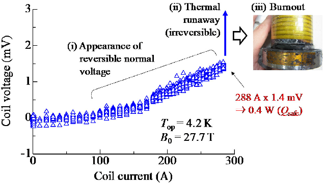
2. The Link Between Thermal and Mechanical Stress
This rapid temperature rise is not just an electrical problem. The localized heating causes thermal expansion. If this expansion is constrained by the surrounding material (which is cooler), it generates significant compressive stress.
To understand this connection quantitatively, we can look at a foundational concept from thermo-mechanics.
Thermally induced ultra high cycle fatigue of copper alloys ...
This paper, while focused on fatigue, provides an excellent explanation of how thermal gradients induce mechanical stress.
Please read the section '2.2 Thermal fatigue' (you may need to scroll to page 14). Focus on: The definition of thermal fatigue and its source: constrained thermal expansion. Equation (2.1), which quantifies the thermal stress resulting from a temperature change: \sigma = E \cdot \alpha \cdot \Delta T / (1 -\nu). This equation is fundamental for understanding how Joule heating creates mechanical stress. The discussion on how material properties (strength, thermal conductivity, expansion coefficient) are crucial for thermal resistance.
The key takeaway is that the temperature increase from Joule heating directly creates a mechanical stress . Furthermore, the high temperatures dramatically reduce the material's yield strength and elastic modulus. This creates a perilous situation where the magnet is simultaneously subjected to increasing thermal stress while its mechanical integrity is compromised, making it vulnerable to failure under the immense Lorentz forces.
3. Hotspots: The Ignition Point for Runaway
Thermal runaway rarely occurs uniformly throughout a coil. It is typically initiated at a hotspot—a small region where the temperature is significantly higher than the average. These can be caused by:
- Geometric Constrictions: Areas where the conductor cross-section is smaller, forcing a higher current density .
- Joints and Connections: Brazed or clamped joints can have higher resistance than the bulk conductor.
- Cooling Deficiencies: Blocked or poorly designed cooling channels.
- Material Defects: Inclusions or voids in the conductor material.

4. Prevention Strategies in Magnet Design
Preventing thermal runaway is a cornerstone of robust magnet design and relies on a multi-pronged approach. Let's examine this through the lens of a practical example from LNCMI.
A novel pulsed magnet for magnetic linear birefringence ...
The 'Foil Coil', developed at LNCMI in Toulouse, is a pulsed magnet designed for room-temperature operation. The paper describing it offers excellent insights into the practical challenges of thermal management.
Please read the following sections, focusing on the thermal aspects: Section III.A ('Design'): Note why room temperature operation was chosen and what constraints this imposes. Section III.B ('Realization'): Pay close attention to the sentence about the holes for optical access increasing the local current density and temperature. This is a key example of a design-induced hotspot. Section III.C ('Tests'): Focus on the discussion about temperature rise, how it's monitored via resistance measurements, and the crucial step of setting an operational temperature limit (60°C average, 80°C local) to protect the insulation. This is a direct example of runaway prevention through operational controls. Section V ('CONCLUSIONS'): Read the paragraph about potential improvements, especially the suggestions for 'forced flow of air or cold nitrogen gas' and modifying the foil to 'maintain the same current density'.
The Foil Coil case study perfectly illustrates the key prevention strategies:
Strategy 1: Material Selection
The choice of conductor is a trade-off between low resistivity (to minimize initial Joule heating) and high mechanical strength (to withstand Lorentz forces). The Foil Coil uses standard copper. For higher-field magnets, high-strength copper alloys like Copper-Silver (CuAg) or Copper-Niobium (CuNb) are used. These materials, which you encountered in a previous module, maintain good conductivity while offering superior mechanical properties, even at elevated temperatures.
Strategy 2: Active Thermal Management
As noted in the Foil Coil paper, simple natural convection is insufficient for high-field or high-repetition-rate operation. Effective prevention relies on aggressive cooling:
- Liquid Nitrogen Pre-cooling: For pulsed magnets, cooling the coil to 77 K before the pulse dramatically reduces the initial resistance (), significantly lowering the total Joule heating during the pulse.
- Forced Convection: As suggested for improving the Foil Coil, using a forced flow of cold nitrogen gas or water through dedicated channels within the winding is essential for removing heat between pulses or during DC operation.
Strategy 3: Intelligent Geometric Design
This involves designing the coil to minimize the creation of hotspots.
- Uniform Current Density: The proposal to modify the Foil Coil's shape to ensure constant current density is a prime example. This avoids concentrating the heating in one area.
- Reinforcing Joints: As seen in the thermal simulation image, adding reinforcement or improving the design of conductor joints can enhance heat transfer and reduce local resistance, mitigating hotspots.
- Optimizing Winding: The way a coil is wound can impact cooling channel effectiveness and create stress concentrations. Your interest in FEM and PMDS software is highly relevant here, as these tools are used precisely to simulate current density, temperature profiles, and stress distributions to optimize the coil geometry.
Strategy 4: Operational Limits and Monitoring
You cannot control what you cannot measure. A critical part of prevention is to operate within safe limits and have a robust monitoring system.
- Setting Limits: The engineers of the Foil Coil set a maximum average temperature of 60°C to "preserve the insulation integrity and the mechanical properties". Exceeding this limit would risk a catastrophic failure.
- Real-time Monitoring: The temperature of the Foil Coil was deduced by measuring its total resistance. In many systems, thermocouples or fiber-optic sensors (like the Fiber Bragg Gratings you'll see later) are embedded in the winding to provide direct temperature readings.
- Safety Interlocks: If the monitoring system detects a temperature approaching the safety limit, it must automatically trigger a shutdown of the power supply and, if necessary, a safe discharge of stored energy to prevent damage.
Test your understanding!
A pulsed magnet designer is considering two modifications to increase the peak field of a coil that is currently limited by its peak temperature rise.
- Replace the standard copper conductor with a high-strength Cu-Ag alloy that has 5% higher resistivity but is twice as strong.
- Reduce the cross-sectional area of the conductor by 10% to fit more turns in the same volume, which increases the field generated per unit of current (B/I).
From a thermal runaway perspective, which of these modifications is more likely to be problematic, and why?
Show answer
Modification #2 is significantly more problematic from a thermal runaway perspective.
Here's why:
- Modification 1 (Changing alloy): The 5% increase in resistivity will lead to a 5% increase in Joule heating () for a given current and geometry. This is a manageable, linear increase.
- Modification 2 (Reducing area): Reducing the cross-sectional area by 10% has a squared effect on heating for a given current density. Resistance is proportional to , so increases by about 11% (). More importantly, to get the same total current, the current density must increase. Since Joule heating power density is proportional to , the heating in the conductor for the same total current would increase significantly. Even if the goal is to use the same current, the increased resistance from the smaller cross-section makes the coil heat up more, pushing it closer to a runaway condition. The goal of adding more turns would likely require even higher currents, exacerbating the problem exponentially.
While the stronger alloy in #1 has higher resistivity, the effect is modest compared to the drastic thermal consequences of reducing the conductor's cross-sectional area in #2.
Conclusion
Key Takeaways:
- Thermal runaway is an unstable positive feedback loop where increasing temperature leads to higher resistance, which in turn generates more Joule heat, causing an uncontrolled temperature spiral.
- The mechanism is initiated at hotspots, which are localized areas of high temperature caused by geometric constrictions, faulty joints, or poor cooling.
- The high temperatures not only risk melting the conductor or insulation but also generate significant thermal stresses and degrade the mechanical strength of materials, leading to combined thermo-mechanical failure.
- Prevention is a holistic design process involving material selection (balancing conductivity and strength), active cooling (LN2, forced convection), intelligent geometry (ensuring uniform current density), and rigorous operational monitoring with strict safety limits.
Next Lesson Preview:
We have now examined several ways a magnet can fail: fatigue, plasticity, creep, and thermal runaway. In the next lesson, we will synthesize this knowledge into a formal design philosophy. We will learn how to apply fracture criteria and appropriate safety factors to calculated stresses to ensure robust magnet design. This is where we transition from understanding failure modes to quantitatively designing systems to avoid them.