Hello! Welcome to the next lesson in our course.
In the previous lesson, we confronted the most extreme failure mode of a pulsed magnet: catastrophic mechanical rupture. We learned to estimate the immense kinetic energy that can be released and explored the principles of blast containment, from thick steel vessels to designing coils for more "graceful" failure. This focused on the large-scale, physical safety of the facility and its personnel.
Now, we shift our attention from ensuring the magnet doesn't destroy the lab to ensuring the magnet's operation doesn't destroy your data. Even when operating perfectly, a pulsed magnet generates a hurricane of electromagnetic fields that can be fatal to the sensitive, low-level signals of a physics experiment. This lesson directly addresses the learning outcome: Analyze sources of electromagnetic interference (EMI) in pulsed magnet systems and describe shielding strategies for sensitive experiments.
We will dissect the origins of this interference, understand how it contaminates your measurements, and—most importantly—learn the practical techniques used by experimentalists to fight back and retrieve clean data from an electrically violent environment.
1. The Anatomy of Electromagnetic Interference (EMI)
To manage EMI, we first need a framework. A standard way to conceptualize any interference problem is the Source-Path-Receiver model.
- Source: The origin of the electromagnetic disturbance. In our case, the primary source is the magnet coil itself, with its enormous, rapidly changing currents () and magnetic fields (). Secondary sources include the high-power switching electronics (ignitrons, thyristors) in the power supply, which can generate high-frequency noise.
- Receiver (or Victim): The sensitive circuit or component we are trying to protect. This is typically your experimental probe, sample wiring, signal amplifiers, and data acquisition systems (e.g., oscilloscopes, lock-in amplifiers).
- Path: The mechanism by which the noise travels from the source to the receiver.
There are four fundamental coupling paths, all of which are relevant in a pulsed field lab.
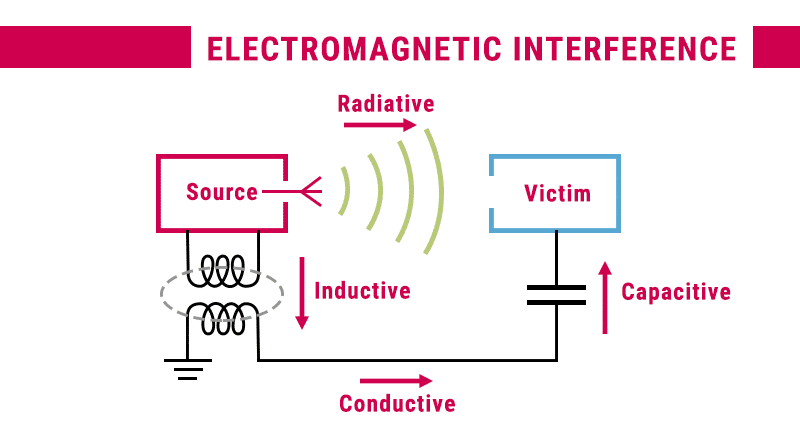
- Inductive Coupling: A time-varying magnetic field passing through a loop of wire induces a voltage (). This is the most dominant and intuitive coupling mechanism in a pulsed magnet. Any loop of wire—from your sample leads to a ground connection—acts as a pickup antenna for the main coil's magnetic field.
- Capacitive Coupling: A time-varying voltage () on one conductor can induce a current in a nearby conductor through stray capacitance. The high voltages present across the coil during a pulse can couple capacitively to nearby probe components.
- Conductive Coupling: Noise currents travel along shared conductive paths, most notably shared ground wires. As we will see, this is one of the most common and insidious sources of interference in real-world lab setups, often creating "ground loops."
- Radiative Coupling: At large distances from the source (the "far-field"), electric and magnetic fields combine to form a propagating electromagnetic wave. While the main pulse itself is a low-frequency event (typically < 1 kHz), the sharp edges from power electronics can radiate high-frequency noise that can be picked up by unshielded cables acting as antennas.
To start building our toolkit against these effects, let's read a short overview.
MT-095: EMI, RFI, and Shielding Concepts
This tutorial from Analog Devices, 'EMI, RFI, and Shielding Concepts', provides a clear breakdown of the EMI problem. We'll focus on the sections defining the mechanisms and the specific strategies to counter magnetic coupling.
Please read two sections from this document: 'EMI COUPLING PATHS' (starts on page 2): This section formally introduces the coupling mechanisms we just discussed. 'REDUCING MAGNETICALLY-COUPLED NOISE' (starts on page 4): Pay close attention to the equation for induced noise voltage and the strategies listed to reduce it, especially reducing loop area.
2. The Unique Challenge: Low-Frequency Magnetic Shielding
From the reading, a key strategy for mitigating inductive coupling is to reduce the loop area (). This is why twisted pair wiring (e.g., twisting the signal and ground leads to your sample) is one of the most effective and fundamental techniques. Each twist reverses the direction of the loop, causing the induced voltages to cancel out.
The other strategy is shielding. However, shielding a low-frequency, intense magnetic field is fundamentally different and more difficult than shielding a high-frequency radio wave. Let's watch a video that explains this crucial distinction.
Shielding Low Frequency Magnetic Fields
The video 'Shielding Low Frequency Magnetic Fields' by OMICRON Lab provides an excellent conceptual and practical demonstration of why typical shielding fails for magnetic fields and what actually works.
Please watch the following segments: Theory of Shielding Effectiveness (05:54 - 07:36): Understand the two mechanisms: reflection and absorption. Key Variables (09:06 - 10:46): Note the dependence on frequency, material properties (permeability \mu, conductivity \sigma), and thickness. The Solution for Low Frequencies (29:55 - 33:25): This is the most important part. See how high-permeability materials don't block the field but redirect it.
To summarize the key insights from the video and other resources:
- High-Frequency Shielding: For RF noise, a simple conductive box (a Faraday cage made of copper or aluminum) is very effective. The shielding works by reflection (the wave bounces off the conductor due to impedance mismatch) and absorption (currents induced in the conductor, known as eddy currents, dissipate the wave's energy; this is related to the skin effect).
- Low-Frequency Magnetic Shielding: For the low-frequency field from the main pulse, both mechanisms fail.
- Reflection is poor because the wave impedance of a near-field magnetic source is very low, close to the impedance of the conductive shield itself. There is no mismatch.
- Absorption is negligible because at low frequencies, the skin depth is very large, often meters thick. Your shield is electrically transparent.
- The Solution: Redirection. The correct approach is to use a material with high magnetic permeability (), such as mu-metal or soft iron. These materials provide a "low-reluctance" path for the magnetic flux lines, effectively gathering them and diverting them around the sensitive volume you want to protect. It's like building a culvert for magnetic flux.

3. EMI in Practice: It's All About the Current
While shielding enclosures are important, a large fraction of real-world EMI problems in a lab setting come down to improper cabling and grounding. In large facilities with equipment spread across a room, it's impossible to have a single, perfect "ground." Different pieces of equipment will have their grounds at slightly different potentials, and these differences drive noise currents through any available path—including the shield of your signal cable.
A paper on EMI management in large physics facilities provides some of the best real-world examples of how these shield currents can create havoc.
Managing Electromagnetic Interference in Large ...
This paper, 'Managing Electromagnetic Interference in Large ...', is essential reading. It uses a simple component, a Current-Viewing Resistor (CVR), to demonstrate in shocking detail how seemingly correct measurement setups can produce wildly inaccurate data due to EMI.
This is a critical part of the lesson. Please read these two sections carefully: 'SIMPLE EMI REAL-LIFE EXAMPLES' (starts on page 3, continues to page 6). Follow the author's investigation into the CVR measurement anomaly. Understand how shield currents and an unintentional 'parasitic bridge' completely corrupted the measurement. This is a masterclass in experimental troubleshooting. 'Common-Mode Isolator' (starts on page 9). This section presents the elegant and powerful solution to the problem identified in the first reading: the Common-Mode Isolator (CMI), or common-mode choke. Understand how it works and study the 'before and after' measurement plots.
Key Takeaways from the Trenches:
The paper you just read is dense with the hard-won wisdom of experimental physicists. Let's distill the most critical points for our pulsed-magnet environment.
1. Ground Loops are Everywhere: When a cable shield is connected to ground at two different points (e.g., at the grounded cryostat and the grounded oscilloscope), it forms a ground loop. The changing magnetic flux from the main magnet pulse will induce a large current in this loop. This is a direct example of inductive coupling.
2. Shield Currents are the Enemy: This loop current, flowing on the outside of your coaxial cable's shield, is the primary villain. Due to the cable shield's finite resistance and transfer impedance, this external current induces a noise voltage on the inside of the cable, which adds directly to your small experimental signal. The CVR example showed this effect can lead to errors of hundreds of percent.
3. The Common-Mode Isolator (CMI) is Your Best Friend: The CMI, or common-mode choke, is the most effective weapon against shield currents. It's simply your signal cable passed through a number of high-permeability ferrite cores.
- How it works: To the differential signal (current going down the center conductor and returning on the inner side of the shield), the CMI is invisible. However, to the common-mode noise current (flowing down the entire cable, shield and all), the CMI presents a very high impedance, effectively choking it off. It blocks the noise without affecting the signal.
- Practicality: CMIs are cheap, easy to make, and incredibly effective. Placing them on all signal cables entering and leaving the high-field area is standard practice in well-run labs.
Test your understanding!
You are trying to measure the voltage across a sample inside a pulsed magnet. Your sample is connected by a 2-meter long coaxial cable to an oscilloscope. The changing B-field induces a 5 A common-mode current on the cable's shield at the pulse frequency of 100 Hz. The cable's transfer impedance at this frequency is dominated by its DC resistance, which is 15 m/m.
What is the approximate magnitude of the noise voltage that will appear at the oscilloscope input, corrupting your signal?
Show answer
The transfer impedance is defined as the voltage induced on the inner conductor per unit of shield current, per unit length.
We can rearrange this to find the noise voltage:
Plugging in the numbers:
A noise signal of 150 mV is enormous! If your real signal is in the microvolt or millivolt range, it will be completely buried. This demonstrates why suppressing the shield current with a CMI is so critical.
Conclusion
We've journeyed from the abstract concept of EMI to the concrete, and often frustrating, reality of experimental physics in a high-field environment. The battle against noise is a constant one, but it can be won with a solid understanding of the underlying physics and a few powerful, practical techniques.
Key Takeaways:
- EMI in pulsed magnet systems is primarily from inductive coupling (from ) and conductive coupling (through ground loops).
- Standard RF shielding with conductive materials is ineffective against low-frequency magnetic fields. You must use high-permeability materials like mu-metal to redirect the magnetic flux.
- Most noise problems are not exotic; they are mundane issues of cabling and grounding. Shield currents flowing in ground loops are the primary culprit for data corruption.
- Your primary weapons are simple and effective:
- Twisted pair wiring to minimize inductive loop area.
- Common-Mode Isolators (Chokes) to block noise currents on cable shields.
- Proper pre-filtering to prevent out-of-band noise from saturating your amplifiers.
Next Lesson Preview:
Having learned to shield a single experiment, we will now zoom out and consider the entire laboratory. How do you arrange a pulsed magnet facility to minimize interference between systems and ensure overall safety? The next lesson will cover the key principles of facility layout for pulsed magnet labs to mitigate stray fields and ensure operational safety. We will look at how the placement of power supplies, magnet cells, and experimental stations is a critical part of a successful high-field laboratory.