Hello! Welcome back to our course.
In our last lesson, we constructed a comprehensive safety protocol to manage the severe electrical hazards of a pulsed magnet facility. We learned how to create a "positively deenergized" state using a layered defense of interlocks, E-stops, and rigorous discharge procedures. This ensures the safety of personnel interacting with the system under normal and maintenance conditions. But what happens when the system itself fails in the most violent way possible?
This lesson addresses the brutal reality of mechanical failure, directly tackling the learning outcome: Estimate the kinetic energy release from a catastrophic coil failure and describe the principles of blast containment. We will investigate how the immense magnetic energy stored in a coil can be violently converted into kinetic energy of shrapnel and pressure waves. Understanding this process is the first step toward designing systems that can contain such an event and protect both personnel and surrounding equipment.
1. The Physics of a Magnet Explosion
At its heart, a pulsed magnet is a container for a vast amount of energy. This energy, stored in the magnetic field, is given by the familiar equation:
where is the coil's inductance and is the current. For a high-field magnet, this can be many megajoules. When a coil fails catastrophically—for example, if the Lorentz forces exceed the ultimate tensile strength of the conductors and reinforcement—this stored energy doesn't just vanish. It is rapidly converted into other forms:
- Heat: through resistive dissipation in the deforming and fragmenting conductors.
- Plastic Deformation: the energy absorbed by the material as it is bent and torn.
- Kinetic Energy: the energy of motion of the coil fragments, which become high-velocity projectiles.
The critical question for safety is how this energy is partitioned. A slow failure might allow most of the energy to dissipate as heat. A rapid, brittle fracture, however, can convert a significant fraction of the magnetic energy into kinetic energy on a millisecond timescale, resulting in a powerful explosion.
2. Modeling Magnetic-to-Kinetic Energy Conversion
To understand this energy conversion process more deeply, we can analyze a simplified model of a solenoid failure. A report from MIT's Plasma Fusion Center provides an excellent theoretical framework for this.
FY1984 REPORT by R.J. Thome, R.D.
This report, 'Safety and Protection of Large Scale Superconducting Magnets', though focused on superconducting magnets, contains a universally applicable analysis of structural failure. We will study the section that models the conversion of magnetic to kinetic energy.
Please read Section 2.0, 'MAGNETIC TO KINETIC ENERGY CONVERSION FOLLOWING STRUCTURAL FAILURE' (from page 5 to 24). Focus on the following: The Model (Section 2.3): Understand the idealized setup of a coil, structure, and 'weak links'. Grasp the force balance equation (2.1) which pits the outward magnetic pressure against the coil's restraining hoop tension and inertia. Dimensionless Parameters: Pay close attention to the definition of the key parameters that govern the system's response: F_0: The relative strength of the winding itself. F_0 > 1 means the winding can support the full magnetic load without its external structure. k^2: The coupling coefficient to a passive secondary circuit. ( au_0 / au_d): The ratio of the characteristic mechanical failure time to the electrical discharge time. The Stability Surface (Fig. 2.4): This is the crucial result. Understand what this 3D plot represents. A design point inside the surface will rupture, while a point outside is 'safe' (it may deform, but won't fragment).
The analysis in the report leads to several profound conclusions about magnet safety:
- Resistive dissipation is too slow. For high-performance magnets, the mechanical failure time (, often ~10 ms) is much shorter than the electrical discharge time (). This means the
($\tau_0 / \tau_d$)ratio is small, and as Figure 2.4 shows, this makes resistive damping ineffective at preventing rupture. You can't dump the energy electrically before the magnet has already blown itself apart mechanically. - "Fail-Safe" Windings are possible. If a coil is designed with enough conductor cross-section and ductility (low current density), it can have . If the external structure fails, the winding itself is strong enough to contain the load, perhaps deforming plastically but not rupturing. This was observed in the real-world failure of a large MHD magnet, described in Section 4.0 of the same report, where the rugged winding limited the energy release.
- Inductive coupling is effective. A tightly coupled, passive secondary winding (high ) can trap a significant fraction of the magnetic energy almost instantaneously, preventing it from being converted to kinetic energy.
3. Estimating Kinetic Energy Release
For a worst-case safety analysis, we must assume the coil does rupture. The model from the MIT report (specifically Figure 2.7) shows that once the ultimate strain of the conductor is exceeded, the conversion of the remaining magnetic energy to kinetic energy becomes unrestrained.
A practical, albeit simplified, approach for a hazard analysis is to assume a certain percentage of the total stored magnetic energy is converted into kinetic energy. This "conversion factor" can range from a few percent to over 50% depending on the specific design and failure mode. A conservative estimate for robustly designed but failing magnets is often in the 10-20% range.
Let's quantify what this means. The energy of an explosion is often compared to its TNT equivalent.
1 kg of TNT releases approximately 4.184 MJ of energy.
Example Calculation:
Consider a large pulsed magnet system at LNCMI storing 10 MJ of energy.
If we assume a conservative 15% conversion to kinetic energy upon catastrophic failure:
Converting this to a TNT equivalent:
This is equivalent to detonating over a third of a kilogram (about 0.8 lbs) of TNT. This is a substantial explosion capable of launching heavy fragments at lethal speeds.
Test your understanding!
A test coil with an inductance of 200 µH is pulsed to a peak current of 50 kA. The total moving mass of the coil windings and immediate reinforcement is 5 kg.
- What is the total magnetic energy stored at peak current?
- Assuming 10% of this energy is converted to kinetic energy of the fragments, what is the TNT equivalent of the explosion?
- If all this kinetic energy were transferred to the 5 kg mass, what would be its initial velocity?
Show answer
-
Stored Energy:
-
TNT Equivalent:
This is small, but still a significant hazard in a lab environment. -
Fragment Velocity:
This is 360 km/h (or 224 mph). A 5 kg object moving at this speed is extremely dangerous.
4. Principles of Blast Containment
Knowing the potential energy release allows us to design systems to contain it. The goal of blast containment is to safely absorb the kinetic energy of fragments and manage the pressure wave from the explosion.
Principle 1: Debris Containment
The primary danger is high-velocity shrapnel. A catastrophic failure turns the magnet's conductors, reinforcement, and support structures into projectiles. The environment at high-energy facilities like the Z-machine at Sandia National Labs provides a stark illustration of this reality.
Pulsed-coil magnet systems for applying 10-30 Tesla ...
This paper describes the pulsed-coil systems developed for the Z-machine. While the goal was successful magnetization, the operational reality of such high-energy experiments provides crucial insight into the destructive aftermath of a pulse.
Please read the final paragraph of Section IV, 'System integration and operation on Z'. This short paragraph powerfully describes the debris problem and the need for containment in a real-world setting.
As the paper states, "Containment of the debris from the energetic release... is a significant problem... Debris mitigation and containment is a critical concern that must be addressed as higher field coil systems are deployed." This is the fundamental motivation for blast containment structures.
Principle 2: Dedicated Containment Vessels
The most direct way to contain an explosion is to enclose the magnet in a robust vessel capable of absorbing the blast energy.

These containment vessels are typically thick-walled steel cylinders or spheres. The design process involves:
- Estimating the maximum credible kinetic energy release (as we did above).
- Calculating the required wall thickness of a given material (e.g., high-strength steel) to absorb this energy without rupturing.
- Often including layers of different materials (e.g., softer steel or wood) to help decelerate fragments and prevent penetration.
Principle 3: Failure Mode Management
Not all failures are equally violent. A key aspect of advanced magnet design is to encourage "graceful" failure modes.
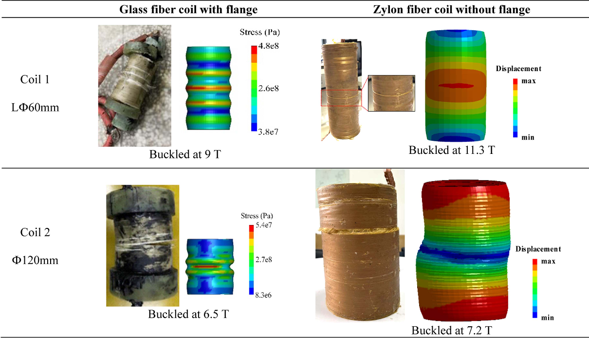
By using ductile conductors (like certain copper alloys) and tough, high-strain reinforcement composites (like Zylon), designers can create coils that are more likely to deform and buckle rather than shatter. This doesn't prevent the failure, but it can significantly reduce the peak kinetic energy released, making the event easier to contain.
Conclusion
We have moved from the abstract danger of stored energy to a concrete analysis of a magnet explosion. The design of a safe, high-field magnet facility is a two-front war: preventing electrical hazards through meticulous protocols, and mitigating the consequences of mechanical failure through robust engineering.
Key Takeaways:
- A catastrophic coil failure rapidly converts stored magnetic energy () into heat, plastic deformation, and kinetic energy.
- The fraction converted to kinetic energy depends on design parameters, with 10-20% being a common estimate for worst-case analysis. This can be equivalent to kilograms of TNT.
- Blast containment is essential and relies on stopping high-velocity shrapnel and absorbing blast energy.
- Containment strategies include thick steel vessels, layered materials, and designing coils to fail in a more "graceful," ductile manner rather than a brittle, explosive one.
The physical safety of the lab is paramount. But even when the magnet operates perfectly, the intense, rapidly changing fields it produces can wreak havoc on the sensitive electronics needed for the actual experiment.
Next Lesson Preview:
In our next lesson, we will shift our focus from macro-scale safety to the micro-scale challenges of measurement. We will analyze sources of electromagnetic interference (EMI) in pulsed magnet systems and describe shielding strategies for sensitive experiments. How do you measure a nanovolt signal from your sample when it's sitting inside a 50 Tesla storm? That is the next challenge we will tackle.