Hello! Welcome to your next lesson in the "Facility Design, Safety, and Global Context" module.
In our previous lesson, we established the fundamental principles of facility layout, focusing on zoning, strategic component placement, and mitigating stray fields to ensure both safety and experimental integrity. We learned that where you put things is the first line of defense against the inherent hazards of a high-field lab.
Today, we build directly upon that foundation to address the learning outcome: Specify high-level facility requirements including electrical power capacity, cooling water systems, and structural support. Now that we know the layout, we'll examine the critical infrastructure and services needed to make that layout functional. These specifications are what transform a building into a world-class research facility like the LNCMI in Toulouse.
1. Electrical Power Capacity: Feeding the Beast
A common misconception is that a pulsed magnet facility needs a dedicated power station. While the peak power during a pulse is enormous (hundreds of megawatts), this energy comes from the capacitor bank, not directly from the grid. The facility's primary electrical requirement is the average power needed to charge the capacitor bank between pulses and to run all auxiliary systems.
Let's estimate the power needed to charge a large capacitor bank. You'll recall from our work on pulsed power systems that the energy stored is . The average power required from the grid to charge the bank is this energy divided by the charging time, .
Consider the 14 MJ capacitor bank at LNCMI-Toulouse.
- If the experimental plan allows for one full-energy pulse per hour (), the average charging power is:
- If a higher repetition rate is needed, say one pulse every 10 minutes (), the power becomes:
This is a remarkably modest power draw, comparable to a few household electric ovens. However, a real facility has multiple magnet cells, each with its own power supply, plus extensive cooling systems, cryogenics, lighting, and control electronics. The total installed power capacity for a large facility is therefore in the range of several megawatts.
For context, the following reading provides figures for both DC and pulsed facilities.
State of the art and developments of high field magnets at ...
Let's revisit the paper by Debray and Frings from LNCMI. It gives concrete numbers for the power and energy needs of high-field facilities, contrasting the continuous power demands of DC magnets with the energy storage approach of pulsed magnets.
Please read Section 3, 'Power and energy requirements for high magnetic fields' (page 5). Focus on: The distinction between power limitation in DC magnets (e.g., 10 to 56 MW) and energy limitation in pulsed magnets. The description of how energy storage (like a capacitor bank) reduces the required power from the public grid by achieving a high average-to-peak power ratio. The diagram and photo of the LNCMI 14 MJ capacitor bank.
The key takeaway is that pulsed facilities trade continuous high power for a large energy storage system. The facility's electrical infrastructure must still be substantial, involving:
- A dedicated substation to step down high voltage from the grid.
- Large transformers and rectifiers to convert AC power to the high-voltage DC needed to charge the capacitors.
- High-voltage switchgear for safely routing power and isolating systems for maintenance.

2. Cooling Systems: The Two Loops
The "cooling water system" requirement is slightly misleading; a pulsed facility actually has two distinct cooling challenges, requiring two different systems:
- Inter-pulse Coil Cooling: Removing the intense heat generated within the magnet coil after a pulse.
- Continuous Facility Cooling: Removing waste heat from auxiliary systems that run continuously.
2.1 Coil Cooling: Liquid Nitrogen (LN2)
As you know from our study of thermal effects, a pulse adiabatically heats the magnet coil. To prepare for the next pulse and to keep the conductor's mechanical properties optimal, this heat must be removed. This is almost universally done with liquid nitrogen (LN2).
Design and Optimization of Force-Reduced High Field ...
The Rembeczki thesis provides an excellent overview of the thermal physics governing pulsed magnets. This section will refresh your understanding of why pre-cooling is so essential.
Please read section '5.5.4 Considerations on Conductor Materials and Cooling' (page 119) and review the associated 'Table B.1' in the appendix. Note the benefits of pre-cooling to 77 K (LN2 temperature) or lower, which include a higher material integral (allowing a larger current pulse) and increased material strength.
The facility requirements for this system are not a water loop, but rather:
- A large, external LN2 storage tank.
- A network of vacuum-insulated cryogenic transfer lines to deliver LN2 to each magnet cell.
- High-capacity vent stacks to safely release the gaseous nitrogen outside the building during the cooling process, preventing an asphyxiation hazard.
2.2 Facility Cooling: The Water Loop
This is the true "cooling water system." It functions like a car's radiator on a massive scale, managing the heat generated by continuously operating equipment such as:
- Capacitor bank chargers and power supplies.
- Control electronics racks.
- Large vacuum pumps.
- Air conditioning for the building itself.
This is a closed-loop system where deionized water is circulated to absorb heat, then pumped to an external unit to reject that heat into the environment.
We can estimate the required flow rate. The heat removed (in Watts) is given by , where is the mass flow rate of the water, is its specific heat capacity (), and is the temperature change of the water. Since (where is density and is volume flow rate), we have:
The facility infrastructure must include:
- A network of large-diameter pipes.
- High-capacity pumps.
- Heat exchangers and cooling towers to transfer the waste heat to the atmosphere.
Test your understanding!
You are specifying a cooling water system for a new set of power supplies that will continuously dissipate 500 kW of heat. Your system uses deionized water () that enters the equipment at 20°C and is designed to exit at a maximum of 35°C (). Calculate the required water flow rate in liters per second.
Show answer
First, we calculate the required volume flow rate in m³/s.
Since 1 m³ = 1000 liters, we convert the flow rate to liters per second:
A flow rate of nearly 8 liters per second requires substantial plumbing, likely several inches in diameter, and powerful pumps, underscoring that even "auxiliary" systems represent a major engineering challenge.
3. Structural Support: Holding It All Together
The structural engineering of a pulsed magnet facility must handle two distinct types of load: immense static weight and powerful dynamic vibrations.
3.1 Static Loads
The sheer mass of the equipment is staggering.
- Magnets: A large pulsed magnet assembly can weigh several tons.
- Shielding: As discussed in the last lesson, magnet cells are shielded with tons of steel and concrete to contain stray fields and provide blast protection. The passive shield for a single magnet can easily exceed 100 tons.
- Power Systems: A large capacitor bank can contain hundreds of individual units, with a total weight of many tens of tons.
The consequence is that the building's foundation must be extraordinary. The floor of a magnet hall is typically a very thick, heavily reinforced concrete slab, often several feet deep, designed to support these massive, concentrated loads without sagging or cracking.
3.2 Dynamic Loads
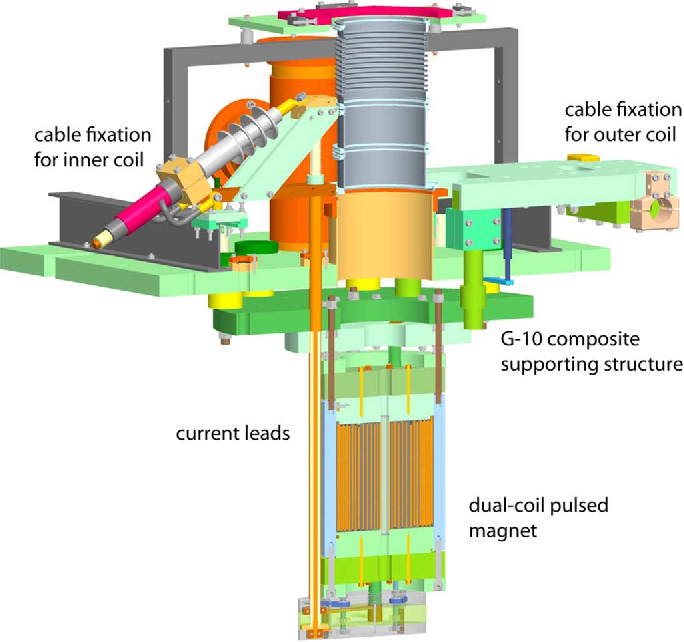
When a magnet is pulsed, the rapid release of energy and the immense Lorentz forces create a significant mechanical shock and vibration that propagates through the structure.
The structural design must prevent these vibrations from affecting sensitive experiments or the rest of the building. Key requirements include:
- Isolated Foundations: Magnet cells are often built on their own concrete foundation, physically decoupled from the foundation of the main building with a vibration-damping gap. This ensures the shock of a pulse is not transmitted to adjacent labs.
- Vibration Damping: The magnets themselves may be mounted on heavy, inert concrete blocks that rest on elastomeric pads to absorb high-frequency vibrations.
- Structural Stiffness: The building frame itself must be exceptionally rigid to minimize flexing and movement.
This is the engineering reason behind the layout principle we discussed previously: the physical separation and isolation of the magnet cells is a primary structural requirement.
Conclusion
Specifying the high-level requirements for a pulsed magnet facility reveals the immense engineering effort that supports the physics experiments. It's a game of managing energy, heat, and force on an industrial scale.
Key Takeaways:
- Electrical Power: The main grid connection is sized for the average power needed to charge the capacitor banks between pulses and run auxiliary systems, typically a few megawatts for a large facility.
- Cooling Systems: A dual approach is required: a cryogenic (LN2) system for removing heat from the magnet coils between pulses, and a continuous closed-loop water system to cool power supplies and other electronics.
- Structural Support: The building must be designed to handle enormous static loads from magnets and shielding, and to isolate the dynamic vibrations caused by the magnetic pulse, often using separate foundations for magnet cells.
Next Lesson Preview:
Now that we have a detailed understanding of the engineering requirements—power, cooling, and structure—that define a high-field facility, we are equipped to make a meaningful comparison of the major labs around the world. In our next lesson, we will do just that, as we compare the capabilities of major pulsed field facilities worldwide (LNCMI, NHMFL, Dresden, Wuhan) in terms of peak fields and pulse durations.