Welcome to your next lesson on building a computer from the ground up. So far in this module, we've focused on the logic for routing and selecting data using Multiplexers and Demultiplexers. These are the "traffic cops" of your future CPU, directing the flow of information. Now, we'll shift from moving data to actually processing it.
Our goal for this lesson is to design a Half Adder. This is the most fundamental arithmetic circuit, and it forms the first building block of the Arithmetic Logic Unit (ALU)—the computational heart of your CPU. You will learn how to take the simple rules of binary addition and translate them into a concrete circuit using the logic gates you're already familiar with.
The Mathematics of Binary Addition
Before we can build a circuit to add numbers, we must first understand the rules it needs to follow. In the decimal system, when you add two numbers like 8 and 4, you get 12. You write down the '2' and 'carry' the '1'. Binary addition works the same way, but is much simpler. When adding two single bits, there are only four possible outcomes:
- , which is
10in binary.
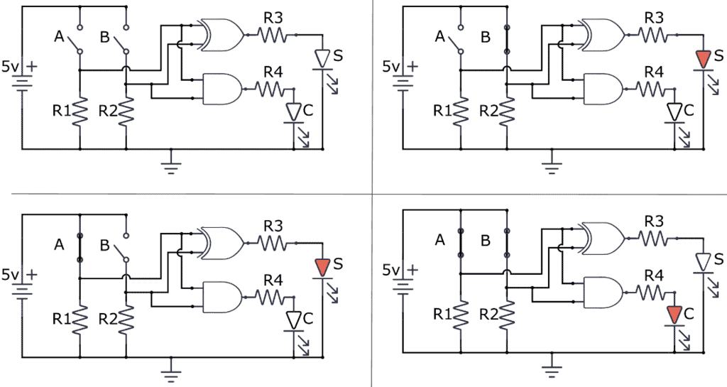
Notice that last case. The result requires two bits: a '0' in the current position and a '1' carried over to the next position. This tells us our circuit needs two inputs (the bits we're adding, let's call them A and B) and two outputs:
- Sum (S): The result for the current bit position.
- Carry (C): The bit that gets "carried over" to the next bit position.
The following article from DigiSim.io provides a great introduction to this concept.
The Half Adder: Your First Step into Digital Logic Design | DigiSim.io
This article introduces the role of the Half Adder and formalizes the rules of binary addition that the circuit must implement.
Read the first two sections, "Defining the HALF_ADDER". Focus on how the four rules of binary addition necessitate two distinct outputs: Sum and Carry.
From Rules to a Truth Table
The most systematic way to design a digital logic circuit is to first create a truth table. This table acts as a formal specification, listing every possible input combination and the required output for each. For the Half Adder, the truth table is a direct translation of the four rules we just discussed.
The image below shows the complete truth table for a Half Adder, along with the standard logic gate diagram we are about to derive.

Take a close look at the truth table. Our task is to find a logic gate or combination of gates that produces the Sum (S) column, and another that produces the Carry (C) column.
Deriving the Logic Gates
Since you're familiar with Boolean math, you know that each logic gate has a unique truth table. By inspecting the output columns of our Half Adder table, we can identify which gates to use. This process of pattern recognition is fundamental to digital design.
Let's analyze the columns one by one:
- The Carry (C) Column: The output is
1only in one case: when both input A AND input B are1. This is the exact behavior of an AND gate. - The Sum (S) Column: The output is
1only when the inputs are different (A=0, B=1 or A=1, B=0). This is the defining characteristic of an XOR (Exclusive OR) gate.
The following video from Sebastian Lague provides an excellent visual walkthrough of this derivation process. He starts with the rules of binary addition, builds the truth table, and then deduces the required gates by inspecting the output columns.
This video segment, from "Exploring How Computers Work", demonstrates how to design the Half Adder circuit from its truth table.
Watch the segment from the beginning. The key part is how the "Carry" column is identified as an AND gate's output and the "Sum" column is identified as an XOR gate's output.
With these two gates identified, we can now state the design formally using Boolean expressions:
- For the Sum:
- For the Carry:
And that's it! By combining one XOR gate and one AND gate, we can successfully implement all the rules for adding two bits. The DigiSim.io article you read earlier also walks through this logic. You can now quickly review that section to solidify your understanding.
The Half Adder: Your First Step into Digital Logic Design | DigiSim.io
This section explicitly connects the Sum and Carry columns of the truth table to their respective logic gates and Boolean expressions.
Read the two short sections, "The Truth Table" and "The Boolean Expression", to see a textual summary of the logic we just derived.
The image below shows the resulting circuit in action for all four possible input combinations. You can trace the logic for each case and see how the lit LEDs for Sum (S) and Carry (C) match the truth table perfectly.
Conclusion
In this lesson, you have successfully designed your first arithmetic circuit. We started with the simple rules of binary addition and systematically translated them into a hardware implementation using basic logic gates. This process—from mathematical rule, to truth table, to Boolean expression, to circuit diagram—is the core workflow of a digital logic designer.
Here are the key takeaways:
- A Half Adder is a combinational circuit that adds two single bits.
- It produces two outputs: a Sum (S) and a Carry (C).
- The Sum output is generated by an XOR gate ().
- The Carry output is generated by an AND gate ().
However, the Half Adder has a critical limitation: it has no input for a "carry-in" bit from a previous, less-significant stage of addition. This means it can only add the very first column of bits in a multi-bit number. To build a circuit that can add numbers larger than one bit, we need to solve this problem.
In the next lesson, you will do just that by designing a Full Adder. You will see how we can combine Half Adders to create a new circuit that accepts a carry-in, allowing us to chain them together to add numbers of any length.