Welcome to the second module of your journey, where we will start building the functional blocks of a computer. In the first module, you mastered the fundamental components, starting from transistors and culminating in the construction of logic gates like AND, OR, NOT, and XOR. You now have the atomic pieces of digital logic.
Today, we move from individual gates to our first truly functional combinational circuit: the Multiplexer, or MUX. Your learning goal is to design a multiplexer using the basic gates you've already built. A multiplexer is a critical component that acts as a digital "data selector" or switch. It is one of the most common and important building blocks in a CPU, used everywhere to control the flow of information. Understanding it is a major step toward designing the data pathways of your own computer.
What is a Multiplexer?
At its core, a multiplexer is a device that selects one of several input signals and forwards the selected input to a single output line. The choice of which input to select is controlled by a separate set of inputs known as select lines.
Think of it like a railroad switch that directs a train from one of several incoming tracks onto a single outbound track. The select lines are the lever that controls the position of the switch. This ability to choose a data source is fundamental for building a CPU, where you constantly need to decide, for example, whether to process data from memory, from a register, or from an external input.
For a formal introduction, the following article provides a great overview.
The Multiplexer (MUX) and Multiplexing Tutorial
This tutorial from Electronics-Tutorials.ws clearly explains the function of a multiplexer using the analogy of a rotary switch.
Please read the introductory section, starting from the definition and continuing down to where it discusses digital multiplexers being made from logic gates. Pay attention to the relationship between the number of inputs and the number of control (select) lines.
As the article mentions, the key relationship is that for data inputs, you need select lines. For our first design, we will start with the simplest case: a 2-to-1 Multiplexer, which has two data inputs and therefore requires just one select line.
Designing a 2-to-1 Multiplexer
Let's design a 2-to-1 MUX from first principles. Our goal is to create a circuit with two data inputs, which we'll call and , one select line , and one output . The behavior we want is:
- If , the output should be equal to the input .
- If , the output should be equal to the input .
1. The Boolean Expression
Knowing your background in Boolean math, we can translate this logic directly into an expression.
- The input is selected when . In Boolean terms, the condition is . So, for this path to be active, we need the term . If is true (meaning ), the output is .
- The input is selected when . The condition is simply . For this path to be active, we need the term .
Since the final output should be either the result of the first case or the second case, we combine them with a logical OR operation. This gives us the complete Boolean expression for a 2-to-1 MUX:
2. The Logic Circuit
This expression is a direct recipe for the circuit diagram:
- We need a NOT gate to generate from .
- We need two AND gates to create the product terms and .
- We need one OR gate to combine the outputs of the AND gates.
The following video provides an excellent visual walkthrough of this exact design process.
Multiplexer Explained | Implementation of Boolean function using Multiplexer
The video "Multiplexer Explained" from the ALL ABOUT ELECTRONICS channel clearly demonstrates the construction of a 2-to-1 MUX.
Please watch the section covering the 2-to-1 MUX, from the beginning of the design. The presenter explains the truth table, derives the Boolean equation, and shows the final logic circuit, which should match our derivation.
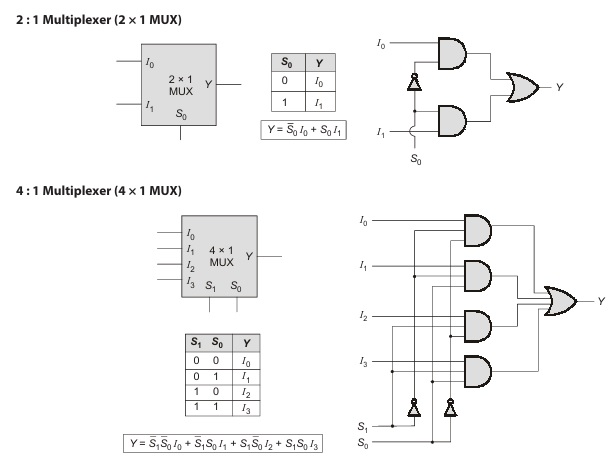
The resulting circuit, along with its block diagram and truth table, is summarized perfectly in the top half of this image:
You may also recall from our lesson on universal gates that any logic function can be built with only NAND gates. The MUX is no exception. The circuit below shows an alternative, common implementation of a 2-to-1 MUX using four NAND gates.

Scaling the Design: The 4-to-1 Multiplexer
A computer needs to select between more than just two sources of data. The same principle we just used can be easily extended. To select from four inputs (), we need two select lines (). The binary value of these two select lines acts as an "address" to choose the input:
- selects .
- selects .
- selects .
- selects .
The Boolean expression expands accordingly:
This requires four 3-input AND gates and one 4-input OR gate. The lower half of the "2:1 and 4:1 Multiplexer" image you just saw shows this exact design. You can also see it explained in the next segment of the video you watched earlier.
Multiplexer Explained | Implementation of Boolean function using Multiplexer
The same video continues by explaining the 4-to-1 MUX.
Now, watch the section on the 4-to-1 MUX, from this timestamp. It follows the same pattern: truth table, Boolean expression, and the resulting logic circuit.
The "Big Picture": Data Buses
Why is this so important for your goal of building a computer? Multiplexers are the key to creating a data bus. A bus is a set of wires that serves as a shared pathway for data between multiple components (like registers, the ALU, and memory). If multiple components try to send data on the same bus at the same time, their signals will conflict. A multiplexer solves this by ensuring only one component's data is placed on the bus at any given clock cycle.
The following video is a fantastic, practical demonstration of this exact problem. It's made in a simulator very similar to the ones you'll be using and directly addresses the challenge of moving data between registers.
Experimenting with Buses and Three-State Logic
This video by Sebastian Lague, "Experimenting with Buses and Three-State Logic," shows why multiplexers are essential for building a computer's data pathways.
Watch the segment from the beginning up to this point. First, he introduces the problem: how to select data from different sources. Next, he builds a multi-bit multiplexer from scratch, just as we've discussed, to solve this problem. Finally, he integrates the MUX into his circuit to enable data transfer between two registers. This provides a powerful visual for how the abstract MUX circuit you designed is used to create a functional computer architecture.
Conclusion
In this lesson, you have designed one of the most versatile components in digital electronics. You've moved from single gates to a circuit that makes decisions and controls the flow of data.
Here are the main takeaways:
- A Multiplexer (MUX) acts as a digital switch, selecting one of its data inputs to route to a single output, based on the value of select lines.
- The logic for a MUX can be derived directly from its truth table into a Boolean expression in sum-of-products form.
- This Boolean expression provides a straightforward blueprint for implementing the MUX with AND, OR, and NOT gates.
- Multiplexers are the enabling technology for data buses, allowing multiple components within a computer to share a common communication pathway without conflict.
You now have a tool for selecting data. In the next lesson, we will explore its logical counterpart: the Demultiplexer (DMUX), a circuit that takes a single data input and routes it to one of several possible output lines. This is equally crucial for tasks like writing data to a specific register or memory location.