Welcome to the final lesson of our first module. In the last session, you mastered a powerful concept: the universality of the NAND gate, using it to construct the three fundamental logic functions. This was a crucial step in understanding how complex digital systems can be built from simple, repeatable units.
Today, we will use that foundational knowledge to build a more specialized, yet incredibly important, component: the Exclusive-OR (XOR) gate. Your learning goal is to implement an XOR gate by combining the basic logic gates you're now familiar with. Understanding the XOR gate is vital, as it forms the very heart of arithmetic circuits in a CPU. This lesson will serve as a bridge between basic logic and the computational circuits you'll start building in the next module.
What is "Exclusive" OR?
The standard OR gate you know is technically an "Inclusive OR" because its output is true if one input is true, or the other is true, or both are true. The XOR gate is different. Its output is true only when its inputs are different from each other. It excludes the case where both inputs are true.
This simple rule makes the XOR gate a perfect "inequality detector," which has profound applications. To get a formal introduction, please start with the following reading.
Exclusive OR Gate Tutorial with Ex-OR Gate Truth Table
This tutorial from Electronics-Tutorials.ws provides a clear definition of the XOR gate and its properties.
Read the introduction starting from the beginning. This part explains the core difference between Inclusive and Exclusive OR. Then, examine the section titled The Digital Logic “Exclusive-OR” Gate to see its symbol, truth table, and Boolean expression.
As you saw, the Boolean expression for a 2-input XOR gate with inputs A and B is:
The symbol for the XOR operation is , so we can write this more compactly as .
Building XOR from its Boolean Expression
That Boolean expression isn't just a mathematical formula; it's a direct set of instructions for building the circuit. Let's break it down:
- We need the term . To get this, we need to take input
A, pass it through a NOT gate, and then feed that result and inputBinto an AND gate. - We need the term . To get this, we take input
B, pass it through a NOT gate, and feed that result and inputAinto a second AND gate. - Finally, we need to add the two terms together (). The
+in this context represents the OR operation. So, we take the outputs from our two AND gates and feed them into an OR gate.
The final output of that OR gate is . This process requires:
- Two NOT gates
- Two AND gates
- One OR gate
The following diagram shows this exact construction.
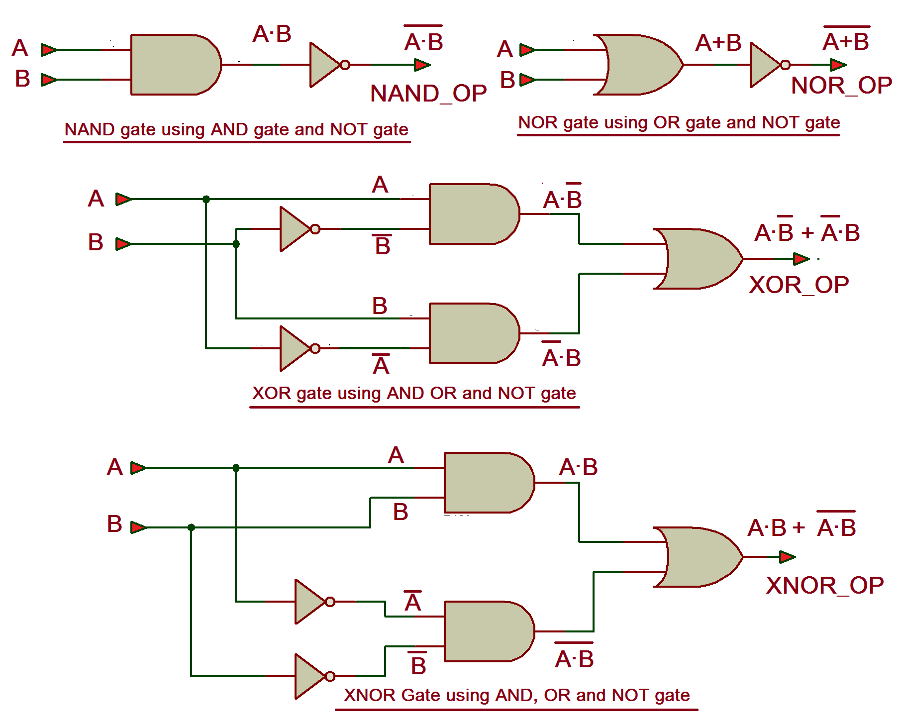
To see this process animated and explained, the following video provides an excellent walkthrough.
Everything about Logic Gates in 12 Minutes | AND, OR, NOT, NOR, NAND, XOR, XNOR Gates
This video from Brain Station Advanced explains all the basic logic gates and shows how to derive a circuit from a Boolean expression.
Please watch the section on the XOR gate, from this point. The presenter first explains the XOR truth table and then demonstrates exactly how the Boolean formula A \cdot \bar{B} + \bar{A} \cdot B is used to design the circuit diagram with AND, OR, and NOT gates.
The NAND-Only Implementation
In the last lesson, you proved that any logic function can be implemented using only NAND gates. It follows, then, that we can also build an XOR gate this way. While you could go through the process of replacing every AND, OR, and NOT gate in the diagram above with its NAND equivalent, there is a more direct and efficient construction that uses only four NAND gates.
This is a classic circuit design in digital electronics.

Proving that this circuit is equivalent to is a great exercise in Boolean algebra, applying De Morgan's laws. For now, what's important is to recognize that this more compact, uniform design is possible, reinforcing the power of universal gates.
The following video shows a comparison of different ways to build an XOR gate, including the 4-NAND-gate method. The narrator also discusses the underlying transistor count, which connects directly to your goal of understanding how hardware works at the lowest levels.
Digital Logic Gates from Transistors, AND, NAND, OR, NOR, XOR, XNOR, Buffer, and Inverter
This video from Global Science Network demonstrates building various logic gates, including several different versions of the XOR gate.
Watch the segment from this timestamp. The presenter demonstrates the 4-NAND gate version of the XOR gate and compares its transistor count (8 transistors) to an alternative design, highlighting the engineering trade-offs involved.
Conclusion
Congratulations on completing the first module! You have successfully journeyed from the physics of transistors to constructing sophisticated logic gates. In this lesson, you focused on the XOR gate, a component that will be indispensable as we move forward.
Here are the key takeaways:
- The Exclusive-OR (XOR) gate outputs
1only when its inputs are different. - Its Boolean expression is , which provides a direct blueprint for building it from AND, OR, and NOT gates.
- Reflecting the principle of universality, the XOR gate can also be constructed efficiently using only four NAND gates.
You are now ready to move from individual gates to functional circuits. The XOR gate is not just a theoretical curiosity; it's the fundamental building block for performing addition in a computer. In our next lesson, you will immediately put the XOR gate to work by combining it with an AND gate to build a Half Adder, the first step in creating an Arithmetic Logic Unit (ALU).