Welcome to the next stage of your journey! In the previous module, you designed and built a powerful combinational circuit: the Arithmetic Logic Unit (ALU). You saw that the ALU's output changes almost instantaneously whenever its inputs change. This is the nature of combinational logic—it has no memory and no sense of time. But a computer can't just be a calculator; it needs to perform operations in a specific sequence, store results, and remember its state from one moment to the next.
This lesson introduces the fundamental concept that makes this order and memory possible: the clock signal. We'll explore how this simple, rhythmic pulse acts as the master conductor for the entire orchestra of digital components in your computer. You'll learn why synchronization is critical, how circuits respond to the clock's "beat," and how this signal ultimately drives the step-by-step execution of a program. This is the bridge from stateless, combinational circuits to stateful, sequential logic—the foundation of memory and processors.
The Heartbeat of a Computer
Imagine an orchestra where every musician plays their next note as soon as they feel like it. The result would be chaos. A computer's logic gates, without a conductor, would behave similarly. Signal changes would ripple through circuits at different speeds, creating a messy, unpredictable system. The clock signal is the conductor's baton, providing a steady, rhythmic beat that tells every component precisely when to act.
This synchronizing pulse is a simple, oscillating digital signal—a square wave that alternates between 1 and 0 at a constant frequency.
To begin, watch this short video from Neso Academy. It provides a clear and concise introduction to the concept of a clock signal and why it's indispensable in digital circuits.
First, watch the segment on why we need clocks to control processes in a sequential circuit. Next, focus on the explanation of what a clock is, defining its wave shape, time period, and frequency. Then, see how the clock is used as an input to control a circuit, allowing it to function only when the clock is high. Finally, the summary at the end reinforces how the clock prevents random, unwanted changes in a circuit's output.
Synchronous vs. Asynchronous Operation
The circuits you've built so far, like the ALU, are combinational. Their outputs depend only on their current inputs. While parts of a CPU are combinational, the system as a whole must be sequential—its next state depends on both current inputs and its previous state.
- Asynchronous circuits: The output changes whenever the inputs change, subject only to the physical propagation delay of the gates. This can lead to problems called race conditions, where signals arriving at different times (due to taking different paths through the logic) can cause temporary, or even permanently incorrect, outputs.
- Synchronous circuits: All state-holding elements update their values simultaneously, controlled by a global clock signal. This ensures that all signals have had enough time to "settle" to their correct values before the next state change is triggered.
The vast majority of modern digital systems, including CPUs, are synchronous because it makes their behavior predictable and reliable.
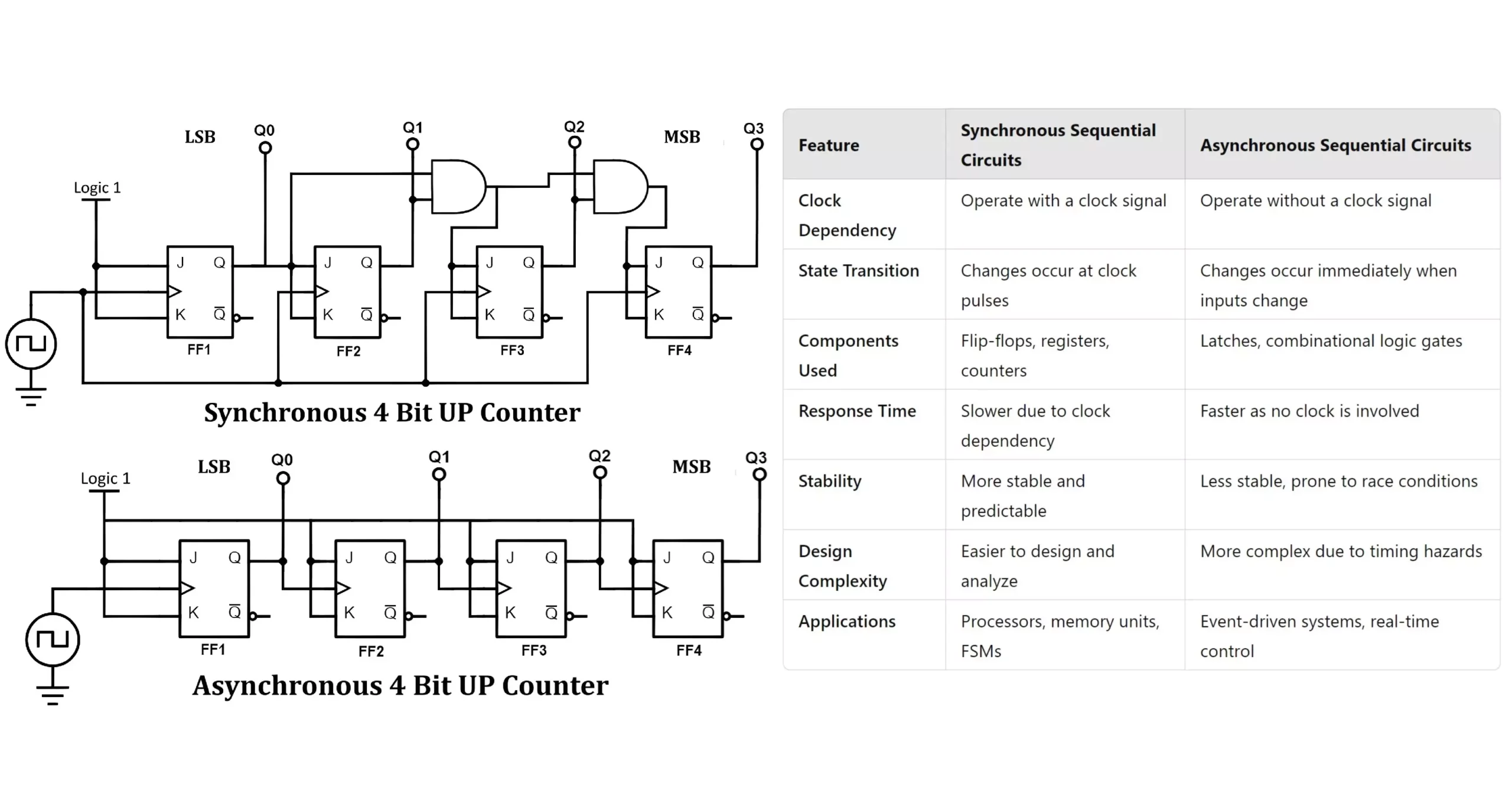
The table in the image highlights the key difference: synchronous circuits are more stable and predictable, which is why they are preferred for complex designs like a CPU.
Responding to the Beat: Level vs. Edge Triggering
How exactly does a component "listen" to the clock? There are two main methods.
1. Level Triggering
A level-triggered circuit is active for the entire duration that the clock signal is at a specific level (usually high, or '1'). While the clock is high, the circuit acts like a transparent window: the output continuously follows any changes at the input.
This can be problematic. If the inputs change multiple times while the clock is high, the output will also change multiple times, which might not be the intended behavior.

2. Edge Triggering
A much more robust and common approach is edge triggering. An edge-triggered circuit only changes its state at the precise instant the clock signal transitions from one level to another. This discrete event acts like a quick snapshot, ignoring any input changes that happen between clock edges.
There are two types of edges:
- Rising Edge: The transition from 0 to 1.
- Falling Edge: The transition from 1 to 0.
By designing circuits to respond only to an edge, we ensure that state changes happen at a single, predictable point in time, giving all other signals in the system the entire clock cycle to stabilize.
The following video brilliantly explains the importance of edges and even shows how you can build a circuit to detect them—a concept that leverages the very physical reality of signal propagation delay you've been learning about.
How the Clock Tells the CPU to "Move Forward"
This video from Core Dumped explains the concept of clock edges and how they are used.
Watch the first part, which introduces the clock signal and highlights the importance of the rising and falling edges. Next, watch the fascinating explanation of how to build a rising edge detector. This demonstrates that even physical limitations like propagation delay can be cleverly harnessed in digital design.
Driving the CPU: The Fetch-Decode-Execute Cycle
Now we can connect this back to your ultimate goal. The clock is what drives the CPU through its fundamental fetch-decode-execute cycle. We need a mechanism that activates the "fetch" circuitry on one clock tick, the "decode" circuitry on the next, and so on.
This is often implemented using a counter and a decoder. The counter increments on each clock edge, and its output is fed into a decoder. The decoder then activates one of its output lines, which in turn enables the correct part of the CPU for that stage of the instruction cycle.
This is a beautiful and simple mechanism for turning a rhythmic pulse into a sequential series of distinct actions. The same video provides an excellent walkthrough of this exact process.
How the Clock Tells the CPU to "Move Forward"
Continue with the Core Dumped video to see how the clock orchestrates the CPU's operation.
Watch the final segment from addressing the main problem. This is a critical part of the lesson. It shows how a binary counter, driven by the clock, and a decoder work together to activate the fetch, decode, and execute stages in sequence. This is a direct preview of the control unit you will build later in the course.
Generating the Clock Signal
You might be wondering where this magical signal comes from. It's not magic, but rather clever electronics. Clock signals are generated by oscillator circuits. While a deep dive into analog electronics is beyond our scope, it's useful to know about the two main types.
This article from Learnabout-electronics.org provides a straightforward overview of clock generation circuits.
First, read the introductory section on Clocks and Timing Signals to understand the three ideal characteristics of a clock signal: constant frequency, fast edges, and correct logic levels. Next, review the section Simple Clock Oscillator. This shows a basic RC (Resistor-Capacitor) oscillator using a Schmitt inverter—a clever use of basic components to create an oscillation. Finally, read about the Crystal Controlled Clock Oscillator. This explains why crystals (like quartz) are used to create the highly stable and accurate clock signals required by real-world computers.
The simple RC oscillator is easy to build but its frequency can drift with temperature and voltage changes. For the precision required in a computer, a crystal oscillator is used. It uses the piezoelectric property of a quartz crystal, which vibrates at a very precise natural frequency when a voltage is applied, to generate an extremely stable clock signal.
Conclusion
You've now been introduced to one of the most fundamental concepts in digital design. Without the clock, a computer would be a chaotic collection of gates. With the clock, it becomes an orderly machine capable of executing complex instructions one step at a time.
Key Takeaways:
- A clock signal is a periodic square wave that synchronizes state changes in a digital system.
- Synchronous design, where components update on a clock signal, prevents race conditions and makes complex circuits predictable and reliable.
- State changes are typically triggered on the rising or falling edge of the clock, not the level, to ensure they happen at a precise moment.
- The clock drives the CPU's operation by stepping a counter through the phases of the fetch-decode-execute cycle.
- Clock signals are generated by oscillator circuits, with crystal oscillators providing the stability needed for modern processors.
You've learned about the "heartbeat" of your future computer. In the next lesson, you will build the first and most basic component that has memory: the SR Latch. This is the first piece of sequential logic that can "remember" a bit of information between the clock's ticks.