Hello! Welcome back to our fourth module on serial communication.
In the last lesson, we built simple blocking (polling) functions to send and receive data over UART. We also discovered their critical weakness: while the CPU is stuck in a polling loop, it can't do other work, and if it's busy with another task when data arrives, that data can be lost. This is unacceptable for most real-world embedded applications, especially in automotive systems where responsiveness is key.
This lesson directly addresses that problem by having you achieve the following outcome: Implement a circular (ring) buffer for efficient data handling. A circular buffer is one of the most fundamental data structures in embedded C programming. It acts as an elastic "shock absorber" between the fast, unpredictable arrival of data from a peripheral and the main application's ability to process it.
1. What is a Circular Buffer?
A circular buffer (or ring buffer) is a fixed-size data queue that operates as if it were connected end-to-end, forming a circle. Data is written to one end (the "head") and read from the other (the "tail"). When either pointer reaches the end of the physical memory block, it simply wraps around to the beginning.
This structure is highly efficient because it avoids the need to shift data around in memory as items are added or removed. It's a perfect implementation of a FIFO (First-In, First-Out) queue.
This animation provides an excellent intuition for how it works.
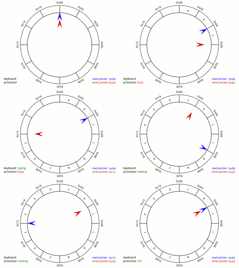
To understand the problems this solves and see a conceptual overview, let's start with a short video.
Interrupt Safe Ring Buffer :: Bare Metal Programming Series 6
The video 'Interrupt Safe Ring Buffer' begins by perfectly recapping the data loss problem we identified with our polling UART driver. It then introduces the ring buffer as the solution.
Watch from 01:13 to 13:28. The first part (until 06:09) demonstrates the data loss problem. The second part introduces the circular buffer concept, explaining its FIFO nature and the crucial idea of having separate 'write' and 'read' interfaces, which is key to making it safe for use with interrupts.
2. The Core Mechanism: Head, Tail, and Wrap-Around
As the video explained, a circular buffer is managed by two indices (or "pointers"):
- Head (or Write Pointer): Points to the next available empty slot where new data will be written. It is only ever advanced by the producer of data (in our case, this will eventually be the UART interrupt service routine).
- Tail (or Read Pointer): Points to the next piece of data to be read. It is only ever advanced by the consumer of data (our main application loop).
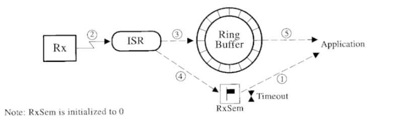
The state of the buffer is determined by the relationship between head and tail:
- Empty: When
head == tail, no unread data is in the buffer. - Full: This is the tricky case. If we allow
headto wrap around and "catch up" totail, the full state would also behead == tail, making it indistinguishable from the empty state.
There are two common strategies to solve this:
- Waste a Slot: The buffer is considered full when
(head + 1) % size == tail. This leaves one slot intentionally unused but simplifies the logic and is naturally safe for concurrent access by a single producer and a single consumer without needing locks. - Use a
fullflag: A separate boolean flag tracks the full state. This uses the entire buffer but requires careful handling to ensure safety, as both the producer and consumer might need to modify the flag.
For our bare-metal, interrupt-driven context, the first approach is generally preferred. The implementation we will study cleverly detects the full condition without explicitly "wasting" a slot by checking the next potential write position.
The video below provides a clear, diagram-based explanation of how these pointers move.
Interrupt Safe Ring Buffer :: Bare Metal Programming Series 6
This segment visually explains how the head and tail indices work, including the conditions for empty/full and the wrap-around mechanism.
Watch from 13:28 to 17:05. Pay close attention to how the wrap-around is achieved. The video mentions two methods: the modulo operator (%) and bitmasking (&). For power-of-two buffer sizes, bitmasking is significantly more efficient on a microcontroller.
3. Hands-On: Implementing the Ring Buffer in C
Now it's time to write the code. We will create a generic, reusable ring buffer module consisting of a header file (ring_buffer.h) for the public interface and a source file (ring_buffer.c) for the private implementation.
Defining the Structure and API
First, let's define what our ring buffer needs to keep track of and what functions we need to interact with it.
Interrupt Safe Ring Buffer :: Bare Metal Programming Series 6
This part of the video walks through the creation of the ring_buffer.h file, defining the data structure and the function prototypes that will form our API.
Watch from 17:05 to 23:15. Follow along and create your own ring_buffer.h file.
For your reference, here is the API we are building:
ring_buffer.h
#include <stdbool.h>
#include <stdint.h>
#include "common_defines.h" // Or your project's common header

// Define the structure for the ring buffer
typedef struct {
    uint8_t* buffer;    // Pointer to the memory buffer
    uint32_t mask;      // Mask for fast wrap-around (size - 1)
    uint32_t read_idx;  // Read index (tail)
    uint32_t write_idx; // Write index (head)
} ring_buffer_t;

// Function prototypes
void ring_buffer_setup(ring_buffer_t* rb, uint8_t* buffer, uint32_t size);
bool ring_buffer_empty(ring_buffer_t* rb);
bool ring_buffer_write(ring_buffer_t* rb, uint8_t byte);
bool ring_buffer_read(ring_buffer_t* rb, uint8_t* byte);
Implementing the Core Functions
Now, let's implement the logic in ring_buffer.c. The implementation details are subtle but critical for ensuring the buffer is safe to use with interrupts.
Interrupt Safe Ring Buffer :: Bare Metal Programming Series 6
This is the most important part of the lesson. The video details the C implementation of the setup, read, and write functions. Pay very close attention to the logic for checking if the buffer is full or empty, and how the indices are advanced.
Watch from 23:15 to 34:42. Implement these functions in your ring_buffer.c file. Notice the use of local copies for the read and write indices—this is a key technique to prevent race conditions when an interrupt can occur at any time.
Key Implementation Points:
- Atomicity: The core principle that makes this interrupt-safe is that the producer (ISR) only ever modifies
write_idx, and the consumer (main loop) only ever modifiesread_idx. They can both read the other's index for comparison, but they never write to it. Reading and writing a 32-bit integer is an "atomic" operation on ARM Cortex-M CPUs, meaning it can't be interrupted halfway through. - Wrap-Around: The wrap-around is done using a bitwise AND with a mask (e.g.,
write_idx = (write_idx + 1) & mask;). This only works if the buffer size is a power of 2 (e.g., 64, 128, 256), but it's much faster than a division/modulo operation. - Full Condition: The
ring_buffer_writefunction checks for the full condition by calculating the next potential write index. Ifnext_write_idx == read_idx, the buffer is full, and the write is rejected. This elegantly prevents overwriting unread data.
4. A Professional Consideration: Sizing Your Buffer
How large should the buffer be? Making it too small risks data loss, while making it too large wastes precious RAM. The correct size depends on two factors:
- Baud Rate: How fast is data arriving?
- Maximum Latency: What is the longest possible time your main loop might take before it gets around to checking the buffer?
Interrupt Safe Ring Buffer :: Bare Metal Programming Series 6
Finally, let's look at how to make an informed decision about the buffer size. This is a practical skill that distinguishes a professional from a hobbyist.
Watch from 49:38 to 52:20. The video explains how to calculate a reasonable buffer size based on your baud rate and expected system latency.
The formula is essentially:
The BaudRate / 10 gives a rough estimate of bytes per second (assuming 8 data bits, 1 start bit, 1 stop bit). You should then round this up to the next power of two to use the efficient bitmasking method.
For example, at 115200 baud and an estimated maximum processing delay of 10ms:
- Bytes per second ≈ 11520
- Bytes in 10ms ≈ 115.2
- The next power of two is 128. A 128-byte buffer would be a sensible choice.
Conclusion
Congratulations! You have now designed and implemented a robust, reusable, and interrupt-safe circular buffer. This is a huge step toward building professional-grade firmware.
Key Takeaways:
- A circular buffer is a fixed-size FIFO queue that efficiently handles data streams between a producer and a consumer.
- It is managed by
head(write) andtail(read) indices that wrap around the buffer. - For power-of-two sizes, using a bitmask (
& (size - 1)) for wrap-around is much more efficient than the modulo operator. - The single-producer, single-consumer model, where the producer only modifies
headand the consumer only modifiestail, provides inherent interrupt safety without needing complex locks. - The required buffer size can be estimated based on the data rate and the maximum expected processing latency.
Preview of the Next Lesson:
We now have the two essential components for robust serial communication: the UART peripheral and a buffer to hold the data. In the next lesson, "Configure UART interrupts for asynchronous, non-blocking data transmission and reception," we will finally connect them. You will write an Interrupt Service Routine (ISR) that automatically places incoming data into the circular buffer, freeing your main loop from the inefficient task of polling and ensuring no data is ever lost.