Hello! Welcome back.
In our last two lessons, we built a polling-based UART driver and then developed a robust circular buffer to overcome its limitations. You learned that polling is inefficient and risks data loss, and that a circular buffer provides a safe, FIFO queue to bridge the gap between fast peripheral data arrival and slower main-loop processing.
Today, we will connect these two concepts using one of the most powerful features of a microcontroller: interrupts. This lesson will enable you to achieve the following learning outcome: Configure UART interrupts for asynchronous, non-blocking data transmission and reception.
By the end of this lesson, you will have a truly professional UART driver. Your main application will be completely decoupled from the low-level mechanics of byte-by-byte serial communication, freeing the CPU to perform other critical tasks—a mandatory requirement for any real-time system, especially in automotive applications.
1. The Anatomy of a Peripheral Interrupt
Before writing any code, it's crucial to understand how an interrupt works. In essence, it's a hardware-driven mechanism that forces the CPU to pause its current task, execute a special function called an Interrupt Service Routine (ISR), and then resume its task exactly where it left off.
For a UART peripheral, this happens in three stages:
- Event Occurs: A specific event happens in the UART hardware. For example, a byte is fully received and moved into the Receive Data Register. This sets a status flag (e.g.,
RXNE- Receive Not Empty). - Interrupt is Asserted: The UART peripheral checks if you've asked it to notify you about this event. If the corresponding interrupt enable bit is set (e.g.,
RXNEIE- RXNE Interrupt Enable), it sends an interrupt signal to the Nested Vectored Interrupt Controller (NVIC). - CPU is Interrupted: The NVIC, which manages all interrupt sources for the CPU, prioritizes the request and, if appropriate, forces the CPU to jump to the pre-defined ISR for that peripheral.
This diagram shows how multiple event flags and their corresponding enable bits are logically combined to generate a single interrupt request from the USART peripheral.
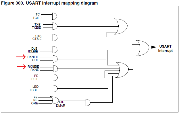
Our job is to configure these enable bits and write the ISR.
2. Configuring the UART Receive Interrupt
Let's start with the most common use case: receiving data without blocking the CPU. We want the MCU to automatically run our code every time a new byte arrives.
To achieve this, we need to do two things: enable the interrupt in the NVIC and enable the specific receive interrupt in the UART peripheral itself.
Receiving Real-Time Data with Interrupts
The article 'Bare Metal STM32 Programming (Part 10): UART Communication' provides an excellent register-level guide for this process. It explains how to set up the NVIC and enable the RXNEIE flag.
Read the section titled 'Receiving Real-Time Data with Interrupts'. Focus on the three key steps shown in the code: NVIC_SetPriorityGrouping, NVIC_SetPriority/NVIC_EnableIRQ, and setting the USART_CR1_RXNEIE bit. Note that a lower priority number means a higher urgency.
Based on the article, here is the sequence to configure the USART1 receive interrupt for your STM32F103 board:
// In your UART initialization function, after basic configuration:

// 1. Enable the USART1 interrupt in the NVIC
// The IRQn for USART1 is USART1_IRQn
NVIC_SetPriority(USART1_IRQn, 0); // Set highest priority
NVIC_EnableIRQ(USART1_IRQn);

// 2. Enable the Receive Not Empty (RXNE) interrupt in the USART1 peripheral
// This bit is in the Control Register 1 (CR1)
USART1->CR1 |= USART_CR1_RXNEIE;
With this configuration, whenever a byte arrives in USART1, the RXNE flag will be set, and the NVIC will immediately call the USART1_IRQHandler() function.
3. Hands-On: The Interrupt-Driven Receive Path
Now we write the code that connects the hardware interrupt to the circular buffer you built in the previous lesson. The ISR will act as the data producer.
The Interrupt Service Routine (ISR)
The ISR is where the immediate, time-critical work is done. Its job is to grab the data from the hardware as quickly as possible and place it in our buffer.
Important Rules for ISRs:
- Keep them short and fast. Do not perform long calculations, delays, or
printfcalls inside an ISR. - Clear the interrupt flag. If you don't, the interrupt will fire again as soon as the ISR finishes, locking your CPU in an endless loop.
For the UART RXNE interrupt, the flag is automatically cleared by reading the Data Register (DR).
Here is the implementation for the ISR. You must place this function in your stm32f1xx_it.c file, or if you are organizing your code, you can have a usart_irq.c and call it from the default handler.
// In your usart.c or a similar file


#include "ring_buffer.h" // Your ring buffer from the last lesson

// Assume you have an RX ring buffer declared globally or passed in
extern ring_buffer_t rx_buffer;

void usart1_rx_interrupt_handler(void)
{
    // Check if the RXNE flag is set
    if ((USART1->SR & USART_SR_RXNE) != 0)
    {
        // The flag is cleared by reading the data from the data register
        uint8_t received_byte = USART1->DR;

        // Write the byte to our ring buffer
        // In a real application, you should check if the write was successful
        ring_buffer_write(&rx_buffer, received_byte);
    }
}
Now, you need to call this handler from the actual ISR function in stm32f1xx_it.c.
// In stm32f1xx_it.c
// ... other handlers

// Declare your handler function
extern void usart1_rx_interrupt_handler(void);

void USART1_IRQHandler(void)
{
  usart1_rx_interrupt_handler();
}
The Main Application (Consumer)
Your main loop is now beautifully simple. It no longer needs to know about UART registers. It just acts as a data consumer, checking the ring buffer for new data at its own pace.
// In main.c


#include "ring_buffer.h"
#include "usart.h" // Your UART driver header


#define UART_RX_BUFFER_SIZE 128
uint8_t uart_rx_buffer_data[UART_RX_BUFFER_SIZE];
ring_buffer_t rx_buffer;

int main(void)
{
    // ... system init ...

    // Setup the ring buffer
    ring_buffer_setup(&rx_buffer, uart_rx_buffer_data, UART_RX_BUFFER_SIZE);

    // Initialize UART with interrupts enabled
    uart1_init(); // This function should contain the NVIC/peripheral setup

    uint8_t byte_to_process;
    while (1)
    {
        // Is there data in our buffer to process?
        if (ring_buffer_read(&rx_buffer, &byte_to_process))
        {
            // Yes! Process the byte.
            // For now, let's just echo it back.
            uart1_send_blocking(byte_to_process); // Using a blocking send for now
        }

        // The CPU is now free to do other work here!
    }
}
You have now implemented non-blocking reception. Data arrives and is buffered by the hardware and your ISR automatically, with zero intervention from your main loop.
4. Hands-On: Asynchronous Transmission
The same principle applies to transmission. A blocking uart_send() function waits in a while loop for the Transmit Data Register to become empty (TXE flag) for every single byte. This can waste thousands of CPU cycles.
With interrupts, we can reverse the producer-consumer model:
- Producer: The main application writes a chunk of data into a transmit circular buffer.
- Consumer: The UART
TXEinterrupt fires whenever the hardware is ready for more data. The ISR then pulls the next byte from the transmit buffer and gives it to the hardware.
The key difference is how the interrupt is managed. We only want the transmit interrupt (TXEIE) to be active when there is actually data in our transmit buffer waiting to be sent.
The Logic:
- The application calls a function like
uart_send_string("Hello"). - This function copies "Hello" into the
tx_buffer. - Crucially, it then enables the
TXEIEinterrupt to "kick-start" the process. - The
TXEinterrupt fires immediately (since the UART is ready). - The ISR reads one byte from
tx_bufferand writes it toUSART1->DR. - The
TXEinterrupt fires again when the hardware is ready. The ISR sends the next byte. - This repeats until the
tx_bufferis empty. When the ISR sends the last byte, it disables theTXEIEinterrupt to stop it from firing again.
Let's implement this.
1. Add a transmit buffer and update your usart_init:
// In main.c or usart.c


#define UART_TX_BUFFER_SIZE 128
uint8_t uart_tx_buffer_data[UART_TX_BUFFER_SIZE];
ring_buffer_t tx_buffer;

// In your UART initialization
ring_buffer_setup(&tx_buffer, uart_tx_buffer_data, UART_TX_BUFFER_SIZE);
2. Create the non-blocking send function:
This function adds data to the buffer and enables the interrupt.
// In usart.c
void uart_send_non_blocking(const uint8_t* data, uint32_t length)
{
    for (uint32_t i = 0; i < length; i++)
    {
        // You should add a check here to ensure the buffer doesn't overflow
        ring_buffer_write(&tx_buffer, data[i]);
    }

    // Enable the TXE interrupt to start the transmission
    USART1->CR1 |= USART_CR1_TXEIE;
}
3. Update the ISR to handle transmit:
// In your usart_irq.c or equivalent
void usart1_tx_interrupt_handler(void)
{
    // Check if the TXE flag is set and the TXE interrupt is enabled
    if ((USART1->SR & USART_SR_TXE) != 0 && (USART1->CR1 & USART_CR1_TXEIE) != 0)
    {
        uint8_t byte_to_send;
        if (ring_buffer_read(&tx_buffer, &byte_to_send))
        {
            // Buffer has data, send the next byte
            USART1->DR = byte_to_send;
        }
        else
        {
            // Buffer is empty, disable the TXE interrupt
            USART1->CR1 &= ~USART_CR1_TXEIE;
        }
    }
}
4. Combine handlers in USART1_IRQHandler:
// In stm32f1xx_it.c
extern void usart1_rx_interrupt_handler(void);
extern void usart1_tx_interrupt_handler(void);

void USART1_IRQHandler(void)
{
  usart1_rx_interrupt_handler();
  usart1_tx_interrupt_handler();
}
Now, your application can call uart_send_non_blocking("some long string"), and it will return immediately while the hardware and ISR handle the entire transmission in the background.
Conclusion
This lesson marks a significant milestone in your journey. You have transitioned from simple, blocking code to a sophisticated, asynchronous, interrupt-driven driver—the standard for professional embedded systems.
Key Takeaways:
- Interrupts decouple the CPU from peripheral operations, enabling efficient multitasking.
- For reception, the ISR is the producer, filling a circular buffer whenever new data arrives from the hardware. The main loop is the consumer.
- For transmission, the main loop is the producer, filling a circular buffer with data to be sent. The ISR is the consumer, feeding bytes to the hardware only when it's ready.
- The Receive Not Empty (
RXNEIE) interrupt should typically be enabled once at initialization. - The Transmit Empty (
TXEIE) interrupt must be managed dynamically: enabled only when there is data to send and disabled as soon as the transmit buffer is empty.
Preview of the Next Lesson:
You now have a powerful and robust communication channel. In the next lesson, "Integrate a circular buffer with UART interrupts to handle continuous data streams," we will build upon this foundation. You will learn to parse incoming data streams to recognize complete commands (e.g., terminated by a newline character), which is the first step toward building the full-featured command-line interface (CLI) you'll complete in this module.