Hello! Welcome back to our module on serial communication.
In the previous lesson, we successfully configured the UART peripheral on your STM32 microcontroller. You now have an initialization function, UART1_Init(), that sets up the necessary clocks, GPIO pins, and communication parameters like the baud rate. The hardware is ready, but it isn't doing anything yet.
Today, we will build upon that foundation to achieve this lesson's learning outcome: Implement blocking (polling-based) functions to transmit and receive data over UART. By the end of this session, you will have written code to send data from your MCU to your computer and receive data back, a fundamental skill for any embedded engineer. This is the classic "Hello, World!" moment for a microcontroller.
1. The Mechanism of Polling: Status and Data Registers
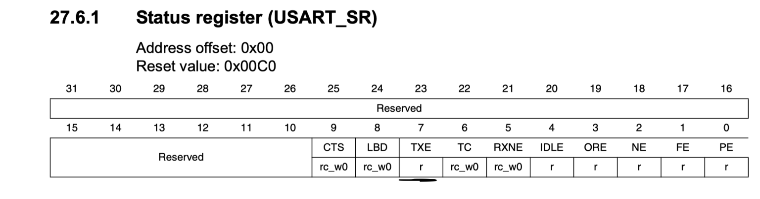
How does the CPU know when it's okay to send a new byte, or when a new byte has arrived? It checks the peripheral's Status Register (SR). For UART communication, two flags in this register are critical:
TXE(Transmit Data Register Empty): When this bit is1, it means the transmit data register is empty and the hardware is ready to accept a new byte for transmission.RXNE(Read Data Register Not Empty): When this bit is1, it means a byte has been successfully received and is waiting in the read data register to be read by the CPU.
The actual data being sent or received is held in the Data Register (DR).
The process, known as polling or blocking, works like this:
- To Transmit: The CPU enters a loop, constantly checking (polling) the
TXEflag. It remains "blocked" in this loop untilTXEbecomes1. Once it is, the CPU writes the byte to the Data Register. - To Receive: The CPU enters a loop, polling the
RXNEflag. It is blocked untilRXNEbecomes1, indicating new data is available. The CPU then reads the byte from the Data Register.
This diagram of the USART_SR register clearly shows the location of these important flags.
2. Bare-Metal Implementation: The Echo Program
Let's translate this polling logic into C code. We will create two functions: one for sending a character (UART_Transmit) and one for receiving a character (UART_Receive).
The following video provides an excellent walkthrough of how to implement these functions at the register level.
STM32 UART: Register Configuration, Transmission and Reception
The video 'STM32 UART: Register Configuration, Transmission and Reception' demonstrates exactly how to build polling-based transmit and receive functions. Pay close attention to how the while loops are used to check the status register flags.
Watch from 16:28 to 18:36. This section covers the creation of a receive_uart function by polling the RXNE flag and a transmit_uart function by polling the TXE flag. This is the core logic for this lesson.
Hands-On Task 1: Create a Bare-Metal Echo
Now, in the project where you created your UART1_Init() function, let's implement this.
-
Create the Transmit Function:
This function will wait until the transmit buffer is empty, then write a character to the data register.void UART_Transmit(uint8_t data) { // Wait until the Transmit Data Register is empty (TXE bit is set) while (!(USART1->SR & USART_SR_TXE)); // Write the data to the Data Register USART1->DR = data; } -
Create the Receive Function:
This function will wait until data has been received, then read it from the data register.uint8_t UART_Receive(void) { // Wait until the Read Data Register is not empty (RXNE bit is set) while (!(USART1->SR & USART_SR_RXNE)); // Read the data from the Data Register return USART1->DR; } -
Implement the Echo in
main():
In yourmainfunction, after calling your initialization code, create an infinite loop that waits to receive a character and immediately sends it back. This "echo" program is a perfect way to test if both transmission and reception are working.int main(void) { // ... System clock and other initializations ... UART1_Init(); uint8_t received_char; while (1) { // Wait for a character to be received received_char = UART_Receive(); // Transmit the same character back UART_Transmit(received_char); } }
Compile this code, flash it to your Blue Pill, and open a serial terminal program (like Tera Term or PuTTY) with a baud rate of 115200. When you type a character in the terminal, you should see it appear right back.
For a complete reference and a refresher on connecting a USB-to-UART adapter, the following article is an excellent resource.
“Bare Metal” STM32 Programming (Part 10): UART Communication
The article 'Bare Metal STM32 Programming (Part 10): UART Communication' provides a full, self-contained echo program example and explains how to connect to the board from your computer.
Review the code snippet in the section right after the heading 'And that’s it!'. This shows a complete polling-based echo program. Then, quickly read the section 'Connecting Your Computer to a UART Interface' if you need a reminder on how to set up your serial terminal.
3. The HAL Approach: HAL_UART_Transmit and HAL_UART_Receive
While bare-metal coding provides an essential understanding, the STM32 Hardware Abstraction Layer (HAL) offers pre-built, robust functions for these common tasks. This is what you will often use in a professional environment to speed up development.
The two key polling functions in the HAL are:
HAL_UART_Transmit(UART_HandleTypeDef *huart, uint8_t *pData, uint16_t Size, uint32_t Timeout)HAL_UART_Receive(UART_HandleTypeDef *huart, uint8_t *pData, uint16_t Size, uint32_t Timeout)
Notice the Timeout parameter. This is a significant advantage over our simple while(1) polling. If data never arrives, a HAL function will give up after the specified timeout instead of freezing the program forever.
STM32 UART (USART) Tutorial + Examples (DMA, Interrupt)
This article from DeepBlue Embedded provides a clear overview of the standard HAL functions for UART communication.
Focus on the table under the heading 'STM32 UART Polling HAL Functions' to see the function prototypes. Then, examine the code under 'STM32 UART Example Code' to see how HAL_UART_Receive and HAL_UART_Transmit are used in practice.
Hands-On Task 2: Re-create the Echo with HAL
Now, let's build the same echo program using the HAL.
-
Open your project's
.iocfile in STM32CubeIDE. If you haven't already, configureUSART1inAsynchronousmode with a baud rate of 115200. Save the file to generate the HAL initialization code. -
In your
main.cfile, implement the echo loop using the HAL functions.int main(void) { // ... HAL_Init(), SystemClock_Config(), MX_GPIO_Init(), MX_USART1_UART_Init() ... uint8_t rx_data; while (1) { // Wait to receive one byte, with a long timeout HAL_UART_Receive(&huart1, &rx_data, 1, HAL_MAX_DELAY); // Transmit that one byte back, with a short timeout HAL_UART_Transmit(&huart1, &rx_data, 1, 100); } }Note that
&huart1is the handle to the UART peripheral, automatically generated by CubeIDE.
Flash this program and test it with your serial terminal. The behavior should be identical to the bare-metal version, but the code is more abstract and portable.
4. The Downsides of Blocking Communication
Polling is simple and effective for basic tasks, but it has two major drawbacks:
- Inefficiency: While the CPU is stuck in a
whileloop waiting forTXEorRXNE, it can't do any other work. This is a significant waste of processing power. - Data Loss: Imagine your program is busy performing a long calculation. If a character arrives on the UART RX line during that time, the CPU isn't polling the
RXNEflag. If a second character arrives before the first one is read from the data register, an overrun error occurs, and the first character is lost forever.
These limitations make simple polling unsuitable for applications that need to perform other tasks while handling continuous or high-speed serial data—a common requirement in automotive and other real-time systems.
Conclusion
Today you took a major step forward by making your microcontroller communicate. You can now send and receive data, a cornerstone of debugging, data logging, and building command-line interfaces.
Key Takeaways:
- Blocking (polling) communication relies on repeatedly checking status flags (
TXE,RXNE) in a loop before reading or writing data. - You can implement this at the register level for maximum control and understanding, or use HAL functions (
HAL_UART_Transmit,HAL_UART_Receive) for faster, more robust development. - A simple "echo" program is the standard method for testing basic two-way communication.
- While simple, polling is inefficient and can lead to data loss in more complex applications.
Preview of the Next Lesson:
To overcome the limitations of polling, we need a way to store incoming data temporarily so the CPU can process it when it's ready. In the next lesson, we will implement a circular (ring) buffer, a fundamental data structure in embedded systems that acts as a bridge between the high-speed arrival of data and the CPU's main processing loop. This is the first step toward building a more powerful, non-blocking communication system.