Hello! Welcome back to our module on Advanced Timers.
In our last lesson, you successfully configured a general-purpose timer to generate a periodic interrupt, making an LED blink without any code in your main while(1) loop. We used pre-calculated values for the prescaler (PSC) and auto-reload register (ARR).
Today, we're going to master the skill behind those numbers. This lesson is dedicated entirely to the learning outcome: Calculate timer prescaler and auto-reload values to achieve a desired frequency. This is a critical skill in embedded systems, as it allows you to precisely control the timing of any periodic event, from sensor sampling to control loop execution. Understanding this calculation is the foundation for generating PWM signals, which is our very next topic.
1. The Timer Calculation Framework
Let's quickly revisit the core components that determine a timer's period. You have a high-frequency clock source, which is "slowed down" by a prescaler to create a more manageable counter clock. The timer's counter increments at this new rate until it reaches the value stored in the auto-reload register, at which point it resets to zero and generates an update event.
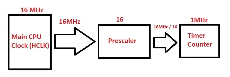
The relationship between these components is defined by this fundamental equation:
Or, if you prefer to think in terms of frequency:
A crucial point to always remember is the +1. The Prescaler (PSC) and Auto-Reload (ARR) are registers that hold values starting from 0. A PSC value of 0 means divide by 1, 71 means divide by 72, and so on.

2. A Strategy for Calculation
Our equation has one target (the desired frequency/period) but two variables we can change: PSC and ARR. This means there can be many correct solutions. The key is to have a strategy for finding a good solution. A common and effective strategy is a two-step process:
Step 1: Choose the Prescaler (PSC) to Set a Convenient Counter Clock
Instead of trying to solve for two variables at once, we first choose a PSC value that scales the main timer clock down to a nice, round number. This intermediate frequency is the speed at which our counter register will actually increment. A target of 1 MHz (for microsecond-level timing) or 10 kHz is common.
Let's assume your STM32F103's timer clock is 72 MHz.
To get a 1 MHz counter clock, we need to divide by 72.
PSC + 1 = 72PSC = 71
To get a 10 kHz counter clock, we need to divide by 7200.
PSC + 1 = 72,000,000 Hz / 10,000 Hz = 7200PSC = 7199
This approach simplifies the problem significantly.
Step 2: Calculate the Auto-Reload Register (ARR) for the Final Frequency
Now that you have a known counter clock frequency, calculating the ARR is straightforward. You just need to figure out how many "ticks" of this new clock fit into your desired period.
ARR + 1 = Desired Period (s) × Counter Clock Frequency (Hz)- ... or
ARR + 1 = Counter Clock Frequency (Hz) / Desired Update Frequency (Hz)
Let's put it all together.
Example Goal: Generate an interrupt every 100ms (10 Hz).
- Timer Clock: 72 MHz.
- Choose PSC: Let's aim for a
10 kHzcounter clock. This gives us good resolution for millisecond-range timings.PSC = (72,000,000 / 10,000) - 1 = 7200 - 1 = 7199.
- Calculate ARR: With a 10 kHz clock, each tick is 0.1ms. How many ticks for 100ms?
ARR + 1 = 10,000 Hz / 10 Hz = 1000.ARR = 999.
- Verification: The timers on the STM32F103 (like TIM2) have 16-bit registers for
PSCandARR. Our values (7199and999) are well below the maximum of 65535. This is a valid and good solution.
The following article demonstrates this exact process with a slightly different choice of prescaler.
STM32 Timer Interrupt HAL Example - Timer Mode LAB
The article 'STM32 Timer Interrupt HAL Example' from DeepBlue Embedded provides a concise, practical walkthrough of this calculation.
Please read the sections titled 'STM32 Timer Calculation & Equation Formula' and 'STM32 Timer Interrupt Example (LAB)'. Notice how they choose a Prescaler of 999 and then solve for the required ARR value (7199) to get the same 100ms interval. This shows there's more than one valid solution.
3. Trade-offs and Limitations
What happens if you need a very long period? Let's say, 2 seconds.
If we use our 10 kHz counter clock from before:
ARR + 1 = 10,000 Hz × 2 s = 20,000ARR = 19,999. This is less than 65535, so it works fine!
Now what about a 10 second period?
ARR + 1 = 10,000 Hz × 10 s = 100,000ARR = 99,999. This value is larger than 65,535! It will not fit in a 16-bit ARR register.
The Solution: When the ARR value overflows, you must go back to Step 1 and choose a larger prescaler. A larger prescaler results in a slower counter clock, which means fewer ticks are needed to cover the same time period.
Let's try again for a 10-second period, this time with a slower counter clock, say 1 kHz.
- Choose a new PSC:
PSC + 1 = 72,000,000 / 1,000 = 72,000.PSC = 71,999. This is still larger than 65,535, so it won't fit in the PSC register.
We need to think differently. We need to find two integers, P = PSC+1 and A = ARR+1, such that:P * A = Period * Clock = 10 * 72,000,000 = 720,000,000
and both P and A must be less than or equal to 65536.
Let's try a PSC value of 35999, which gives P = 36000.
A = 720,000,000 / 36000 = 20,000.- This gives us
ARR = A - 1 = 19,999.
This is a valid solution! PSC = 35999 and ARR = 19,999 are both less than 65535 and will produce a 10-second period.
This illustrates the core trade-off:
- Small Prescaler: Faster counter clock, higher timing resolution, but shorter maximum period.
- Large Prescaler: Slower counter clock, lower timing resolution, but longer maximum period.
This concept of resolution versus frequency is explained well with a counting analogy in the following video. While it's framed in the context of PWM (our next topic), the principle is identical.
The video 'STM32 Guide #3: PWM + Timers' from Mitch Davis provides an intuitive explanation of the trade-off between resolution and frequency.
Watch from 5:25 to 8:36. Focus on the analogy of counting to a small number versus a large number. Counting to a larger number ('higher resolution') takes longer, reducing the overall frequency of the cycle. This is the same trade-off we face when choosing our ARR and PSC values.
4. Your Turn: Practice Problems
Now it's time to solidify your understanding. Calculate the PSC and ARR values for the following scenarios, assuming a 72 MHz timer clock and 16-bit registers. Aim for solutions where neither PSC nor ARR exceeds 65535.
- Goal: An update frequency of 400 Hz.
- Goal: An update period of 5 seconds.
- Challenge: What is the longest possible period you can achieve with a general-purpose timer on this MCU?
Take a few minutes to work through these on paper.
Click to see solution for Problem 1 (400 Hz)
- Strategy: Let's target a 1 MHz counter clock for high resolution.
- PSC:
PSC = (72,000,000 / 1,000,000) - 1 = 71. - ARR:
ARR = (1,000,000 / 400) - 1 = 2500 - 1 = 2499. - Result:
PSC = 71,ARR = 2499. Both values are valid.
Click to see solution for Problem 2 (5 seconds)
- Strategy: A 5-second period is long, so we'll likely need a large prescaler. Let's try to get a 10 kHz counter clock first and see if it works.
- PSC:
PSC = (72,000,000 / 10,000) - 1 = 7199. - ARR:
ARR = (10,000 * 5) - 1 = 50,000 - 1 = 49,999. - Result:
PSC = 7199,ARR = 49,999. Both values are valid and fit within 16-bit registers.
Click to see solution for Problem 3 (Longest Period)
- Strategy: To get the longest period, we must maximize both the
PSCandARRregisters. - PSC: Max value is
65535. - ARR: Max value is
65535. - Calculation:
Period = ((65535 + 1) * (65535 + 1)) / 72,000,000 Period = (65536 * 65536) / 72,000,000 = 4,294,967,296 / 72,000,000- Result:
Period ≈ 59.65seconds.
Conclusion
You now have the knowledge and strategy to precisely control the frequency of any STM32 timer. This is a skill you will use constantly as an embedded engineer.
Key Takeaways:
- The relationship between period, clock frequency, PSC, and ARR is defined by a core equation.
- A robust strategy is to first select a Prescaler (
PSC) to create a convenient counter clock frequency (e.g., 10 kHz), then calculate the Auto-Reload (ARR) value. - If the required
ARRvalue exceeds the register's maximum size (e.g., 65535), you must use a largerPSCvalue (i.e., a slower counter clock). - There is an inherent trade-off between the maximum period a timer can generate and its timing resolution.
Preview of the Next Lesson:
With this mastery of timer frequency calculation, we are perfectly prepared for the next step. In our next lesson, we will configure a timer channel in Output Compare mode to generate a PWM signal. You will see that the timer's period, which you now know how to calculate, directly determines the PWM signal's frequency.