Hello! Welcome to the first lesson in our third module on Advanced Timers.
In the previous module, we laid a solid groundwork with core system components. You learned to configure system clocks, handle user input with debounced external interrupts, and you became familiar with the SysTick timer, using it to create a reliable time base for your debouncing logic. This interrupt-driven approach is key to writing efficient firmware.
Today, we'll expand on that knowledge. While SysTick is excellent as a simple system-wide time base, STM32 microcontrollers are equipped with much more powerful and flexible general-purpose (GP) timers. Our goal for this lesson is to master the learning outcome: Configure a general-purpose timer to generate periodic update interrupts for timed tasks. Think of this as creating a highly precise, configurable "heartbeat" for your application, allowing you to schedule tasks without ever blocking the CPU in a while loop.
1. From SysTick to General-Purpose Timers
SysTick is a part of the ARM Cortex-M core itself, designed to be a simple timer primarily for providing a "tick" for a Real-Time Operating System (RTOS). General-purpose timers, on the other hand, are peripherals designed by the chip manufacturer (STMicroelectronics, in our case) and offer a much wider range of features, which we'll explore in this module.
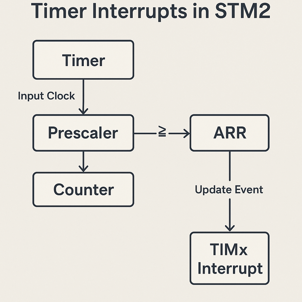
Today's focus is on the most fundamental function of a GP timer: generating a periodic interrupt. The core principle involves three key components working together:
- Prescaler (PSC): A divider that slows down the timer's input clock.
- Counter (CNT): A register that increments at the rate of the prescaled clock.
- Auto-Reload Register (ARR): The value that the counter counts up to. When the counter reaches this value, it "rolls over" or "resets" to zero.
This "rollover" event is called an Update Event, and it's what we use to trigger an interrupt.
2. The Math Behind the Heartbeat
To get a precise time interval, we need to calculate the correct values for the Prescaler (PSC) and the Auto-Reload Register (ARR). The formula is straightforward:
Let's break this down with an example. Assume your STM32F103 is running with a system clock of 72 MHz. The general-purpose timers on the APB1 bus (like TIM2, TIM3, TIM4) are also clocked at 72 MHz if the APB1 prescaler is 1.
Goal: Generate an interrupt every 500ms (a frequency of 2 Hz).
-
Choose a Prescaler (PSC): It's common practice to choose a PSC value that brings the counter clock to an easy-to-manage frequency, like 10 kHz.
- Counter Clock = Timer Clock / (PSC + 1)
- 10,000 Hz = 72,000,000 Hz / (PSC + 1)
- PSC + 1 = 72,000,000 / 10,000 = 7200
- PSC = 7199
-
Calculate the Auto-Reload (ARR): Now that our counter increments 10,000 times per second, how many increments do we need to wait for 500ms?
- Number of Ticks = Desired Period × Counter Clock
- Number of Ticks = 0.5 s × 10,000 Hz = 5000
- The ARR value is this number of ticks minus one, because the counter starts at 0.
- ARR = 5000 - 1 = 4999
By setting PSC = 7199 and ARR = 4999, the timer will trigger an update interrupt exactly every 500 milliseconds.
To solidify this theory, the following article from ST provides another clear example of this calculation.
How to generate a one second interrupt using an STM32 timer
This ST Community article, 'How to generate a one second interrupt using an STM32 timer,' explains the theory and calculations for setting up a periodic interrupt. It reinforces the concepts of the timer clock source, prescaler, and auto-reload register.
Please read Section 2, 'Theory'. It walks through the same calculation process we just discussed, but for a 1-second interval on a different STM32 chip. The principles are identical and seeing it applied in a slightly different context will deepen your understanding.
3. Implementing a Timer Interrupt
Now that we have the theory, let's see how it's done in practice. We will use the STM32CubeIDE and the HAL library to configure the timer and write the interrupt handler code.
The process involves:
- Configuring the system clock.
- Selecting a timer (e.g., TIM2) and setting its clock source to
Internal Clock. - Entering the calculated
PrescalerandCounter Period(ARR) values. - Enabling the timer's global interrupt in the NVIC (Nested Vectored Interrupt Controller) settings.
- Generating the code.
In the C code, two things are essential:
- Starting the timer in interrupt mode:
HAL_TIM_Base_Start_IT(&htimX); - Implementing the callback function that executes when the interrupt occurs:
HAL_TIM_PeriodElapsedCallback(TIM_HandleTypeDef *htim).
This video from Digi-Key offers a professional and clear explanation of timer interrupts and the corresponding HAL implementation.
Getting Started with STM32 and Nucleo Part 6: Timers and Timer Interrupts | Digi-Key Electronics
This video, 'Getting Started with STM32 and Nucleo Part 6: Timers and Timer Interrupts,' provides an excellent conceptual overview and practical demonstration of setting up a timer interrupt.
Please watch from 10:40 to 14:29. This section covers: The concept of a timer update interrupt. How to calculate the auto-reload value (Counter Period) for a desired interval. The specific HAL functions to start the timer (HAL_TIM_Base_Start_IT) and handle the callback (HAL_TIM_PeriodElapsedCallback). Pay close attention to how the callback function is implemented to toggle an LED.
4. Your Turn: Create a Periodic LED Toggle
It's time for you to apply these concepts. Your task is to configure a general-purpose timer to toggle the onboard LED (PC13) on your Blue Pill board at a frequency of 1 Hz (meaning it should toggle every 500ms).
Step 1: Calculation
First, perform the calculations for a 500ms interrupt period with a 72 MHz timer clock. We already did this above, so you should have:
- Prescaler (PSC): 7199
- Counter Period (ARR): 4999
Step 2: Project Setup in STM32CubeIDE
- Create a new STM32 project for your
STM32F103C8T6. - RCC: Set High Speed Clock (HSE) to
Crystal/Ceramic Resonator. - SYS: Set Debug to
Serial Wire. - Clock Configuration: Go to the tab, select
HSE, and set HCLK to72MHz. - Pinout & Configuration -> Timers:
- Select a timer, for example,
TIM2. - Under
Clock Source, selectInternal Clock.
- Select a timer, for example,
- Parameter Settings for TIM2:
- Set Prescaler (PSC) to
7199. - Set Counter Period (Auto-Reload Register) to
4999.
- Set Prescaler (PSC) to
- NVIC Settings Tab:
- Find the
TIM2 global interruptrow and check theEnabledbox.
- Find the
- GPIO Configuration:
- Click pin PC13 and configure it as
GPIO_Output.
- Click pin PC13 and configure it as
- Generate Code: Name your project and generate the initialization code.
Step 3: Writing the Application Code
Open main.c in your newly generated project.
-
Start the timer. In your
main()function, after theMX_..._Init()calls but before thewhile(1)loop, add the following line to start TIM2 in interrupt mode./* USER CODE BEGIN 2 */ HAL_TIM_Base_Start_IT(&htim2); /* USER CODE END 2 */ /* Infinite loop */ while (1) { /* USER CODE END WHILE */ /* USER CODE BEGIN 3 */ } -
Implement the callback. At the bottom of
main.c, in theUSER CODE BEGIN 4section, add the implementation for the period elapsed callback. This function will be called automatically every 500ms./* USER CODE BEGIN 4 */ void HAL_TIM_PeriodElapsedCallback(TIM_HandleTypeDef *htim) { // Check if the interrupt came from TIM2 if (htim->Instance == TIM2) { HAL_GPIO_TogglePin(GPIOC, GPIO_PIN_13); } } /* USER CODE END 4 */The
ifstatement is good practice to ensure you're handling the correct timer, which becomes essential when you use multiple timers in a project.
Step 4: Build, Flash, and Test
Compile your project, flash it to your Blue Pill board, and reset it. The onboard LED on PC13 should now be blinking steadily, turning on for 500ms and off for 500ms. Your while(1) loop is completely empty, yet your program is performing a periodic task. This is the power of interrupt-driven design.
Conclusion
Excellent work. You have successfully configured a general-purpose timer to act as a precise, periodic scheduler for a task. This is a cornerstone skill in embedded systems, forming the basis for everything from reading sensors at a fixed interval to running control loops in automotive systems.
Key Takeaways:
- General-purpose timers offer more flexibility and features than the core SysTick timer.
- The Prescaler (PSC) and Auto-Reload Register (ARR) are used to configure the exact period of a timer interrupt.
- The periodic interrupt is triggered by the timer's Update Event.
- In HAL, you start the timer with
HAL_TIM_Base_Start_IT()and handle the event in theHAL_TIM_PeriodElapsedCallback()function. - This interrupt-driven approach allows for periodic tasks to run efficiently without blocking the main CPU loop.
Preview of the Next Lesson:
Now that you can create a periodic interrupt, we will explore another powerful mode of the timer peripheral. In the next lesson, we will configure a timer channel in Output Compare mode to generate a Pulse Width Modulation (PWM) signal. This will allow you to control the brightness of an LED or the speed of a motor, moving from simple on/off control to precise analog-like behavior.