Hello! Welcome to the next step in our exploration of synchronous communication protocols.
In the previous lesson, we configured the I2C peripheral on your STM32 microcontroller, diving deep into the register-level setup for clocks, GPIOs, and timing. You now have a peripheral that is enabled and ready for action.
Today, we will build directly on that foundation. Our goal is to implement I2C master write and read transactions, handling start/stop conditions and ACKs. We will move from a configured but silent peripheral to one that can actively communicate on the bus. We'll construct the low-level functions required to send and receive data, which we will then use in the next lesson to control the I2C LCD in your kit.
1. The Anatomy of an I2C Transaction
Before writing any code, we need a crystal-clear picture of the sequence of events that constitutes an I2C transaction. At its core, every transaction is a sequence of states on the SDA and SCL lines, governed by the master.
To get a solid conceptual overview of this sequence, let's watch a short video that explains the structure of I2C data frames.
I2C Frame structure Understanding | I2C data transmission
The video 'I2C Frame structure Understanding' from Foolish Engineer provides an excellent, easy-to-follow breakdown of the bits and bytes that make up write and read operations.
Watch the entire video from 00:43 to 09:58. Pay close attention to the analogy used, as it clearly separates the key phases of a transaction: Start, Slave Address + R/W bit, ACK, Register Address (for register-based devices), Data, and Stop.
As you saw, a transaction is not just a single blast of data. It's a carefully choreographed dance of signals. Let's visualize the two main types of transactions with timing diagrams.
Master Write Transaction: This is the simpler case, where the master sends data to a slave.
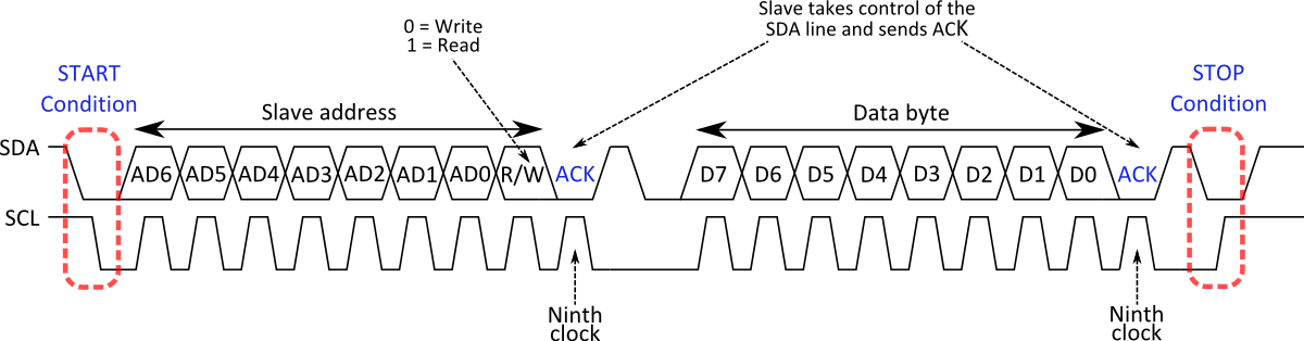
Master Read Transaction: This is more complex because the master must first tell the slave what it wants to read. This involves a write phase followed by a read phase, linked by a special "Repeated Start" condition.

2. Implementing a Master Write Transaction
Now, let's translate the write transaction diagram into C code. Our approach will be to create small, reusable functions for each step of the protocol. We'll be polling the I2C status registers (SR1 and SR2) to know when each step is complete.
The article "STM32 I2C Register Configuration Tutorial" from ControllersTech provides a clear guide for creating these functions.
STM32 I2C Register Configuration Tutorial - ControllersTech
This article details the register-level implementation of the core I2C functions. We'll focus on the functions for starting, writing, addressing, and stopping.
Read the sections 'I2C START', 'I2C WRITE', and 'Send Slave Address'. Focus on which bits in the Control Register (I2C_CR1) are set to initiate an action, and which bits in the Status Register (I2C_SR1) are checked to confirm completion.
Let's break down the logic for each function based on the reference manual and the article.
Function 1: I2C_Start()
- Action: Set the
STARTbit (bit 8) in theI2C_CR1register. This commands the peripheral to generate a Start condition on the bus. - Verification: Poll the
SB(Start Bit) flag (bit 0) in theI2C_SR1register. This flag is set by hardware once the Start condition is successfully sent. The program must wait in a loop until this bit is 1.
void I2C_Start(void) {
    I2C1->CR1 |= (1 << 8); // Set the START bit in CR1
    while (!(I2C1->SR1 & (1 << 0))); // Wait for SB bit to be set (start condition generated)
}
Function 2: I2C_Address()
- Action: After the Start, the master must send the slave's address. You write the 7-bit slave address, shifted left by one bit, into the Data Register (
I2C_DR). The least significant bit (bit 0) is the R/W bit (0 for write, 1 for read). - Verification: Poll the
ADDR(Address Sent) flag (bit 1) inI2C_SR1. This is set when the slave acknowledges its address. - Cleanup: The
ADDRflag must be cleared by software. This is done by readingI2C_SR1followed by readingI2C_SR2.
void I2C_Address(uint8_t address) {
    I2C1->DR = address; // Send the slave address
    while (!(I2C1->SR1 & (1 << 1))); // Wait for ADDR bit to be set
    // Clear ADDR bit by reading SR1 and SR2
    uint8_t temp = I2C1->SR1 | I2C1->SR2;
}
Function 3: I2C_Write()
- Verification: Before sending data, you must ensure the Data Register is empty. Poll the
TXE(Transmit data register Empty) flag (bit 7) inI2C_SR1. - Action: Write the byte of data to the
I2C_DR. - Verification (for multi-byte): If you are sending more data, you can simply wait for
TXEagain. To confirm the byte has been fully transmitted and acknowledged, you can wait for theBTF(Byte Transfer Finished) flag (bit 2) inI2C_SR1.
void I2C_Write(uint8_t data) {
    while (!(I2C1->SR1 & (1 << 7))); // Wait for TXE bit to be set (DR is empty)
    I2C1->DR = data; // Load data into DR
    while (!(I2C1->SR1 & (1 << 2))); // Wait for BTF bit to be set (transfer finished)
}
Function 4: I2C_Stop()
- Action: Set the
STOPbit (bit 9) in theI2C_CR1register. The hardware will then generate the Stop condition on the bus, and this bit is automatically cleared.
void I2C_Stop(void) {
    I2C1->CR1 |= (1 << 9); // Set the STOP bit in CR1
}
With these four functions, you can now construct a complete write transaction:
// Example: Write 0x01 to a device at address 0x4E
I2C_Start();
I2C_Address(0x4E); // 0x4E is address with R/W bit = 0
I2C_Write(0x01);
I2C_Stop();
3. Implementing a Master Read Transaction
Reading from a slave is more nuanced. As shown in the timing diagram, it requires a write phase to specify the target register, followed by a read phase initiated by a repeated start.
The most complex part is managing the ACK/NACK signals. When reading multiple bytes, the master must ACK every byte except the last one. Before reading the final byte, the master must signal this to the slave by sending a NACK, followed by a STOP.
Let's turn back to the ControllersTech article for a detailed explanation of the read logic. This is the most challenging part of today's lesson.
STM32 I2C Register Configuration Tutorial - ControllersTech
This section of the article breaks down the complex logic for single-byte and multi-byte read operations. Pay very close attention to how and when the ACK bit is cleared and the STOP condition is generated.
Read the sections 'I2C READ', 'Read Data from Slave Device', and the two comments below that discuss the slave address for reading (Address+0x01) and the specific timing for single-byte reads on the F103. This is critical for getting your code to work on your Blue Pill board.
Based on the article, let's outline the logic for a generic I2C_Read function.
Key Concepts for Reading:
- Repeated Start: To switch from writing the register address to reading data without another device interrupting, you call
I2C_Start()again before aI2C_Stop(). - Read Address: To signal a read, you send the slave address with the R/W bit set to 1. This is typically done by
(slave_address << 1) | 1. If your address variable already includes the shifted value, it's justaddress | 1. - Receiving Data: You wait for the
RXNE(Read data register Not Empty) flag (bit 6) inI2C_SR1to be set, then read the data fromI2C_DR. - ACK/NACK Control:
- To ACK a received byte (and ask for more), the
ACKbit (bit 10) inI2C_CR1must be set. - To NACK the final byte (to signal the end of the read), the
ACKbit must be cleared before the final byte is received.
- To ACK a received byte (and ask for more), the
The logic differs slightly for reading a single byte versus multiple bytes, as described in the reference manual and the article. Here is a high-level function combining the logic for a complete read operation:
// This is a conceptual function combining all steps.
void Read_From_Device(uint8_t device_address, uint8_t reg_address, uint8_t* buffer, uint8_t size) {
    // 1. Start and write the register address we want to read from
    I2C_Start();
    I2C_Address(device_address); // Address with write bit (0)
    I2C_Write(reg_address); // Send the register address, but use a variant of I2C_Write that doesn't wait for BTF

    // 2. Send a repeated start and the address with the read bit set
    I2C_Start();
    // The I2C_Read function handles the rest
    I2C_Read((device_address | 1), buffer, size); // Address with read bit (1)

    // The I2C_Stop is handled inside the full I2C_Read implementation
}
Implementing a robust I2C_Read function that handles both single and multi-byte cases requires careful state management. The code in the "I2C READ" section of the LINK article you just studied is an excellent, complete reference for this.
Conclusion
Today, we have bridged the gap between theory and practice by implementing the fundamental I2C transaction functions. You now understand the precise sequence of register manipulations and status flag checks required to master the I2C bus.
Key Takeaways:
- An I2C write transaction involves:
START->ADDRESS+W->ACK->DATA->ACK->STOP. - An I2C read transaction is a two-phase process: a write to set the register pointer, followed by a
REPEATED START, and then the read sequence:ADDRESS+R->ACK->DATA->ACK/.../NACK->STOP. - Communication is orchestrated by setting bits in control registers (
I2C_CR1) and polling flags in status registers (I2C_SR1). Key flags areSB,ADDR,TXE,RXNE, andBTF. - The master controls acknowledgements during a read. It must send a
NACKbefore reading the final byte to signal the end of the transfer. - Clearing the
ADDRflag requires a specific read sequence ofI2C_SR1andI2C_SR2.
Preview of the Next Lesson:
With our low-level functions ready, we are prepared to talk to a real device. In the next lesson, we will interface with an I2C LCD. We will apply the I2C_Write functions we've built to send initialization commands and display data on the screen. We will also see how a logic analyzer can be an invaluable tool for debugging I2C traffic, which will complete the final learning outcome for this module.