Hello! Welcome to our next lesson on synchronous communication protocols.
In our last session, we successfully configured the SPI peripheral on your STM32 board. You learned how to set it up as a master device, define the clock speed and mode, and most importantly, how to implement a flexible software pattern for managing the Chip Select (CS) line for multiple slaves.
Today, we will build directly on that foundation to achieve this lesson's learning outcome: Implement blocking functions to transmit and receive data with an SPI peripheral. We will write the C code that performs the actual data exchange, fitting it neatly within the Select/Deselect structure we designed previously. By the end of this lesson, you'll be able to communicate with a typical SPI slave device like a sensor or memory chip.
1. The Core of SPI: A Full-Duplex Exchange
Before we dive into functions, it's crucial to remember that SPI is fundamentally a full-duplex protocol. This means that for every bit the master sends to the slave on the MOSI line, a bit is simultaneously sent back from the slave to the master on the MISO line.
This exchange happens through a conceptual shift register in both the master and slave. When the master toggles the clock, it pushes a bit out (MOSI) and simultaneously latches a bit in (MISO). After 8 clock pulses (for 8-bit data), the master and slave have effectively swapped a byte of data.
This has a key implication: you can't just "receive" data without also "transmitting" something. To read from a slave, the master must send out "dummy" data (often 0x00 or 0xFF) just to generate the necessary clock pulses that allow the slave to send its data back.
2. How "Blocking" Functions Work: The Polling Mechanism
The functions we'll use today are "blocking" or "polled." This means the function will not return (it "blocks" your program's execution) until the entire SPI transaction is complete.
How does the microcontroller know when the transaction is done? It continuously checks status flags in the SPI peripheral's Status Register (SR).
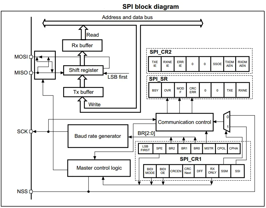
The three most important flags for polling are:
TXE(Transmit buffer empty): This flag is set when the Tx buffer is empty and ready to accept the next piece of data to be sent. A blocking transmit function waits for this flag before loading data into the data register.RXNE(Receive buffer not empty): This flag is set when a piece of data has been fully received from the MISO line and is waiting in the Rx buffer to be read by the CPU. A blocking receive function waits for this flag before reading the data.BSY(Busy flag): This flag indicates that the SPI peripheral is in the middle of a communication. The function will wait for this flag to be cleared to ensure the transaction is truly finished.
A blocking function is essentially a while loop that spins until these flags indicate completion. For example, a simplified register-level transmit/receive function looks like this:
// This is a conceptual example. We will be using the HAL equivalent.
uint8_t SPISend(uint8_t data) {
    // Wait until the transmit buffer is empty (TXE flag is set)
    while (!(SPI1->SR & SPI_I2S_FLAG_TXE));

    // Send the data
    SPI1->DR = data;

    // Wait until the receive buffer is not empty (RXNE flag is set)
    while (!(SPI1->SR & SPI_I2S_FLAG_RXNE));

    // Wait until the SPI peripheral is no longer busy
    while (SPI1->SR & SPI_I2S_FLAG_BSY);

    // Return the data that was simultaneously received
    return (SPI1->DR);
}
This low-level view is crucial for understanding what the high-level HAL functions are doing for you behind the scenes. It's not magic; it's just efficient polling of hardware status bits.
3. Implementing Blocking Transfers with STM32 HAL
Fortunately, the HAL abstracts away this direct register polling. It provides three main blocking functions for SPI communication. Let's look at how to use them.
The following article provides an excellent reference for these functions.
The article 'SPI Peripheral In STM32F103' from GetToByte clearly lists the key HAL APIs we will be using.
Scroll down to the 'HAL APIs Involved' section. Familiarize yourself with the function prototypes for HAL_SPI_Transmit and HAL_SPI_TransmitReceive. Pay attention to their parameters: the SPI handle, pointers to data buffers, data size, and a timeout value.
Now, let's see these functions in action with a real-world example: communicating with an external EEPROM chip. This is a common task and a great way to practice.
Getting Started with STM32 and Nucleo Part 5: How to Use SPI | Digi-Key Electronics
The video 'Getting Started with STM32 and Nucleo Part 5: How to Use SPI' from Digi-Key provides a perfect hands-on demonstration of these HAL functions.
Watch the video from 11:08 to 14:45. The presenter demonstrates a complete sequence of communicating with an SPI EEPROM. As you watch, observe how each HAL function is used for a specific purpose within the CS select/deselect block.
Let's break down the process step-by-step, just as shown in the video.
Step 1: Transmit-Only Operation
You often need to send a command to a slave device without needing an immediate response. For this, HAL_SPI_Transmit() is ideal.
Example: Sending a "Write Enable" command to an EEPROM.
// Assume hspi1 is your SPI handle and you have a CS management function.
uint8_t write_enable_cmd = 0x06; // A common command for EEPROMs

SPI_SelectSlave(SLAVE_EEPROM); // Pull CS LOW

// Transmit the command byte
HAL_SPI_Transmit(&hspi1, &write_enable_cmd, 1, 100); // 1 byte, 100ms timeout

SPI_DeselectSlave(SLAVE_EEPROM); // Pull CS HIGH
Even though we're "transmitting only," remember that the slave is still sending data back on the MISO line. With this function, the HAL simply ignores the received data.
Step 2: Receive-Only Operation
To read data, you must send dummy bytes to generate the clock signals. The HAL_SPI_Receive() function handles this for you. It transmits dummy data (internally) while filling your receive buffer with the data coming from the slave.
Example: Reading the EEPROM's status register after sending a "Read Status" command.
uint8_t read_status_cmd = 0x05;
uint8_t status_value = 0;

SPI_SelectSlave(SLAVE_EEPROM);

// First, transmit the command to tell the slave what you want to read
HAL_SPI_Transmit(&hspi1, &read_status_cmd, 1, 100);

// Now, receive the 1-byte status value.
// HAL sends a dummy byte automatically to clock the data in.
HAL_SPI_Receive(&hspi1, &status_value, 1, 100);

SPI_DeselectSlave(SLAVE_EEPROM);

// The 'status_value' variable now holds the content of the EEPROM's status register.
Step 3: Simultaneous Transmit and Receive
For maximum efficiency, HAL_SPI_TransmitReceive() leverages the full-duplex nature of SPI. You provide both a transmit buffer and a receive buffer. The function sends the data from your transmit buffer while simultaneously filling the receive buffer with data from the slave.
This is the most common function you'll use when communicating with devices like sensors, where you send a register address to read from and immediately receive the data from that register.
Example: A complete loopback test. In a real-world scenario where you don't have two STM32s, you can test your SPI setup by physically connecting the MOSI pin to the MISO pin on your board. Whatever you transmit will be immediately received.
The following article provides a full code example for this.
Let's return to the 'SPI Peripheral In STM32F103' article for a complete code example.
Review the full code under the 'CODE' heading. Notice how tx_buffer and rx_buffer are declared, and then passed to HAL_SPI_TransmitReceive. This is a clear and concise example of a blocking transmit/receive operation.
Here's how you would structure that loopback test in your main.c:
// In main() after peripheral initialization

// 1. Define your buffers
uint8_t tx_data[] = {0xAA, 0x55, 0xDE, 0xAD, 0xBE, 0xEF};
uint8_t rx_data[6]; // Must be the same size as tx_data

// 2. Select your "slave" (in this case, just managing the CS pin for consistency)
SPI_SelectSlave(SLAVE_LOOPBACK);

// 3. Perform the transaction
HAL_StatusTypeDef status = HAL_SPI_TransmitReceive(&hspi1, tx_data, rx_data, 6, 200);

// 4. Deselect the "slave"
SPI_DeselectSlave(SLAVE_LOOPBACK);

// 5. Verify the result
if (status == HAL_OK) {
    // Set a breakpoint here and inspect the 'rx_data' array in your debugger.
    // If MOSI is connected to MISO, rx_data should be identical to tx_data.
    for (int i = 0; i < 6; i++) {
        if (tx_data[i] != rx_data[i]) {
            // Error!
            break;
        }
    }
}
This loopback test is an invaluable first step in verifying your hardware setup and basic SPI code before you attempt to communicate with a more complex external peripheral.
Conclusion
You have now mastered the implementation of blocking SPI communication. You understand not just how to use the HAL functions, but also why they work the way they do—by polling status flags in the hardware.
Key Takeaways:
- Blocking SPI functions halt CPU execution until the data transfer is complete by polling status flags like
TXE,RXNE, andBSY. - SPI is full-duplex: data is always being sent and received simultaneously.
HAL_SPI_Transmit()is for sending data when the return data is not needed.HAL_SPI_Receive()is for reading data; it requires transmitting dummy bytes to generate the clock.HAL_SPI_TransmitReceive()is the most efficient function, managing both transmit and receive buffers in a single call.- All data transfer calls must be wrapped within
SPI_SelectSlave()andSPI_DeselectSlave()to control the target device.
Preview of the Next Lesson:
With SPI communication now under your belt, you are ready to tackle the second major synchronous protocol. In the next lesson, we will begin our exploration of I2C. You will learn about its unique two-wire architecture, addressing scheme, and how its master-slave communication differs from SPI.