Hello! Welcome back to our course on professional embedded systems engineering.
In the previous lesson, we configured the CAN peripheral's hardware acceptance filter. Your STM32 board is now set up to automatically accept messages with the ID 0x321 and discard all others. This is a crucial step for building efficient and robust CAN nodes. However, simply accepting a message isn't enough; our firmware needs to react to it.
This lesson bridges that gap. Our learning outcome is to set up a CAN receive interrupt (FIFO pending) to process incoming messages. We will move away from polling (constantly checking for data) and embrace an interrupt-driven approach. When a valid message passes our filter and arrives in the receive FIFO, the CAN peripheral will automatically trigger an interrupt, calling our code to handle the message immediately. This is the standard, professional way to manage asynchronous events like message reception, and it's fundamental to real-time systems.
1. The Interrupt-Driven Reception Mechanism
In an automotive network, a CAN bus can be flooded with messages. Polling a status register to see if a new message has arrived would be incredibly inefficient and waste valuable CPU time. The correct approach is to let the hardware notify the CPU when a message is ready.
This process involves three key steps:
- Enable the Interrupt Controller: We must configure the Nested Vectored Interrupt Controller (NVIC) to allow the CAN peripheral to interrupt the CPU.
- Activate the Interrupt Source: We need to instruct the CAN peripheral itself to generate an interrupt signal when a message is pending in the receive FIFO.
- Implement the Callback Function: We must write the code that will execute when the interrupt occurs. This is where we'll read and process the message.
The diagram below shows the hardware logic inside the STM32's bxCAN peripheral. To generate a "FIFO message pending" interrupt, two conditions must be met: the FMP (FIFO Message Pending) status flag must be set by hardware, and the corresponding FMPIE (FIFO Message Pending Interrupt Enable) control bit must be set by our software.
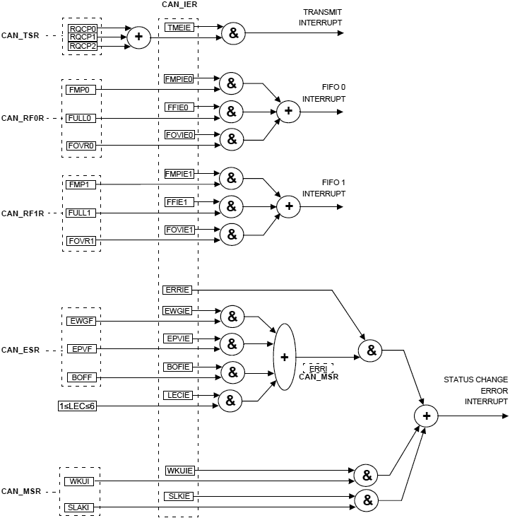
Our task is to configure these pieces correctly using the STM32 HAL.
2. Enabling and Activating the Receive Interrupt
First, we need to perform the initial setup in STM32CubeMX to enable the interrupt line in the NVIC. Then, in our code, we'll use a HAL function to activate the interrupt generation within the CAN peripheral.
The following article, which you've seen before, clearly outlines these two steps.
STM32 CAN Bus Communication Tutorial (Normal Mode)
The ControllersTech tutorial provides a concise guide on enabling CAN receive interrupts. We will use it to understand the CubeMX configuration and the required HAL function.
Please read the section titled "Receiving CAN Data in STM32". Focus on two key parts: The CubeMX screenshot showing the CAN1 RX0 interrupt being enabled in the NVIC settings. The code snippet for HAL_CAN_ActivateNotification(). This function is what sets the FMPIE bit we saw in the diagram, arming the interrupt.
As the article explains, enabling the interrupt in CubeMX makes the CPU aware of the interrupt source, while calling HAL_CAN_ActivateNotification() tells the CAN hardware to actually start generating interrupt signals when a message arrives in the specified FIFO.
3. Implementing the Interrupt Callback
When the CAN receive interrupt is triggered, the CPU jumps to a predefined Interrupt Service Routine (ISR) provided by the HAL. This ISR performs some low-level tasks (like identifying the source of the interrupt) and then calls a user-defined callback function.
For a message received in FIFO 0, this function is HAL_CAN_RxFifo0MsgPendingCallback(). The HAL provides a __weak default implementation of this function, which does nothing. Our job is to provide our own strong implementation to handle the event.
Inside the callback, we must do two things:
- Retrieve the message: Call
HAL_CAN_GetRxMessage()to copy the message header and data from the CAN FIFO into our own variables. This is a critical step, as it also clears the pending interrupt flag. Failing to do this can result in the ISR being called continuously. - Process the message: Act on the received data. For now, we will simply toggle an LED to get immediate visual feedback that our reception logic is working.
This video provides a practical demonstration of coding the callback function.
STM32 CAN Communication Explained | Send & Receive Data Between Two Microcontrollers
The following video segment from ControllersTech shows exactly how to implement the callback to retrieve and use the incoming CAN message.
Watch the clip from 06:43 to 08:40. Pay attention to: The structure of the HAL_CAN_RxFifo0MsgPendingCallback function. The call to HAL_CAN_GetRxMessage to get the header and data. The simple logic used to process the RxData array.
4. Hands-On Implementation: Bringing it all Together
Now, let's modify your existing project to handle message reception via interrupts.
-
Enable Interrupts in CubeMX:
- Open your project in STM32CubeIDE and double-click the
.iocfile. - In the Pinout & Configuration view, navigate to Categories > Connectivity > CAN.
- Go to the NVIC Settings tab.
- Tick the checkbox for CAN1 RX0 interrupts to enable it.
- Save the
.iocfile (Ctrl+S) to generate the updated initialization code.
- Open your project in STM32CubeIDE and double-click the
-
Declare Global Variables for Reception:
Inmain.c, in the private variables section (/* USER CODE BEGIN PV */), declare global variables to hold the header and data of incoming messages./* USER CODE BEGIN PV */ CAN_TxHeaderTypeDef TxHeader; uint8_t TxData[8]; uint32_t TxMailbox; CAN_RxHeaderTypeDef RxHeader; // Add this line uint8_t RxData[8]; // Add this line /* USER CODE END PV */ -
Activate Interrupt Notification:
In yourmain()function, find where you configured the filter and started the CAN peripheral. Immediately after theHAL_CAN_Start()call, activate the FIFO 0 message pending interrupt./* USER CODE BEGIN 2 */ // ... your CAN_FilterTypeDef configuration is here ... if (HAL_CAN_ConfigFilter(&hcan, &sFilterConfig) != HAL_OK) { /* Filter configuration Error */ Error_Handler(); } // Start the CAN peripheral if (HAL_CAN_Start(&hcan) != HAL_OK) { /* Start Error */ Error_Handler(); } // Activate the CAN receive interrupt if (HAL_CAN_ActivateNotification(&hcan, CAN_IT_RX_FIFO0_MSG_PENDING) != HAL_OK) // Add this block { /* Notification Error */ Error_Handler(); } /* USER CODE END 2 */ -
Implement the Callback Function:
Scroll to the bottom ofmain.cand add your implementation of the callback inside the/* USER CODE BEGIN 4 */section./* USER CODE BEGIN 4 */ /** * @brief Rx Fifo 0 message pending callback. * @param hcan pointer to a CAN_HandleTypeDef structure that contains * the configuration information for the specified CAN. * @retval None */ void HAL_CAN_RxFifo0MsgPendingCallback(CAN_HandleTypeDef *hcan) { // Retrieve the message from FIFO 0 if (HAL_CAN_GetRxMessage(hcan, CAN_RX_FIFO0, &RxHeader, RxData) == HAL_OK) { // Successfully received a message. For now, just toggle the onboard LED. // PC13 is the onboard LED on the Blue Pill board. HAL_GPIO_TogglePin(GPIOC, GPIO_PIN_13); } } /* USER CODE END 4 */ -
Build and Flash:
Compile and flash the code to your Blue Pill board. Your previous code is still transmitting a message with ID0x321every second. Your filter is configured to accept it. Now, with the interrupt enabled, each time your board receives its own message, the onboard LED (PC13) should toggle. Since you are transmitting every second, you should see the LED blink at a 1 Hz rate (on for 1s, off for 1s).
Conclusion
Congratulations! You have successfully implemented an interrupt-driven CAN reception routine. Your application no longer wastes time polling for data; instead, the hardware efficiently notifies it the moment a relevant message arrives. This is a cornerstone of professional embedded firmware design.
Key Takeaways:
- Interrupt-driven reception is far more efficient than polling for handling asynchronous CAN messages.
- The setup involves three steps: enabling the interrupt in the NVIC (via CubeMX), activating the notification source with
HAL_CAN_ActivateNotification(), and implementing theHAL_CAN_RxFifo0MsgPendingCallback()function. - It is crucial to call
HAL_CAN_GetRxMessage()within the callback to retrieve the data and clear the pending interrupt status.
So far, we have only toggled an LED to confirm reception. In our next lesson, we will focus on what to do with the actual content of the message. You will learn to parse a received CAN message to extract its ID and data payload, enabling you to build much more complex and interactive automotive applications.