Hello! Welcome back to our professional embedded systems course.
In our last lesson, we successfully configured a CAN receive interrupt. Your board now gets a hardware notification whenever a message matching your filter arrives, and the callback function toggles an LED. This is a fantastic step forward, as it confirms your reception pipeline is working efficiently.
However, in any real application, simply knowing a message arrived isn't enough. We need to know what the message says. This lesson will teach you how to do just that.
Our learning outcome is to parse a received CAN message to extract its ID and data payload. We will dive into the callback function you created, retrieve the complete message, and learn how to pull out the sender's ID and the specific data bytes that carry the valuable information. This skill is the key to creating interactive and intelligent CAN nodes for any automotive or industrial system.
1. The Anatomy of a Received Message
When the HAL_CAN_RxFifo0MsgPendingCallback is triggered, our first job is to retrieve the message from the hardware FIFO. The HAL library provides the function HAL_CAN_GetRxMessage() for this purpose. This function populates two structures that you've already declared:
CAN_RxHeaderTypeDef RxHeader: A structure that holds the message's metadata.uint8_t RxData[8]: A byte array that holds the message's data payload.
Let's look at the critical fields inside the RxHeader structure:
StdId: The 11-bit standard identifier of the message.ExtId: The 29-bit extended identifier (used ifIDEis set for extended frames).IDE: Identifier Extension bit. Tells you whether the frame uses a standard (CAN_ID_STD) or extended (CAN_ID_EXT) ID.RTR: Remote Transmission Request bit. Tells you if this is a data frame (CAN_RTR_DATA) or a remote frame (CAN_RTR_REMOTE).DLC: Data Length Code. An integer from 0 to 8 indicating how many bytes in theRxDataarray are valid. This is a crucial field to check to avoid reading garbage data.
The following article section provides a clear, practical example of how these structures are used within the callback.
STM32 CAN Bus Communication Tutorial (Normal Mode)
This section from the ControllersTech tutorial clearly shows the C code for receiving a CAN message. It's a perfect reference for understanding how HAL_CAN_GetRxMessage populates the header and data structures.
Please read the section titled "Receiving CAN Data in STM32" again, but this time, focus on the code within the HAL_CAN_RxFifo0MsgPendingCallback function. Notice how it declares RxHeader and RxData, calls HAL_CAN_GetRxMessage to fill them, and then immediately checks RxHeader.StdId to identify the message.
2. The Professional Challenge: Signal Packing
In simple examples, you might send one value per message, like a temperature reading. In a real automotive system, this would be incredibly wasteful. A single 8-byte CAN message payload often carries multiple pieces of information, a technique called signal packing.
For example, a single message from an engine control unit (ECU) could contain:
- Engine RPM (16 bits)
- Throttle Position (8 bits)
- Coolant Temperature (8 bits)
- A few status flags (1 bit each)
These signals are packed together into the 8-byte (64 bit) payload according to a precise map. In the automotive industry, this map is formally defined in a DBC (Data Base CAN) file, which acts as the universal dictionary for the vehicle's network.
The image below illustrates this concept perfectly. It shows three different signals of varying bit lengths packed into a 6-byte payload.
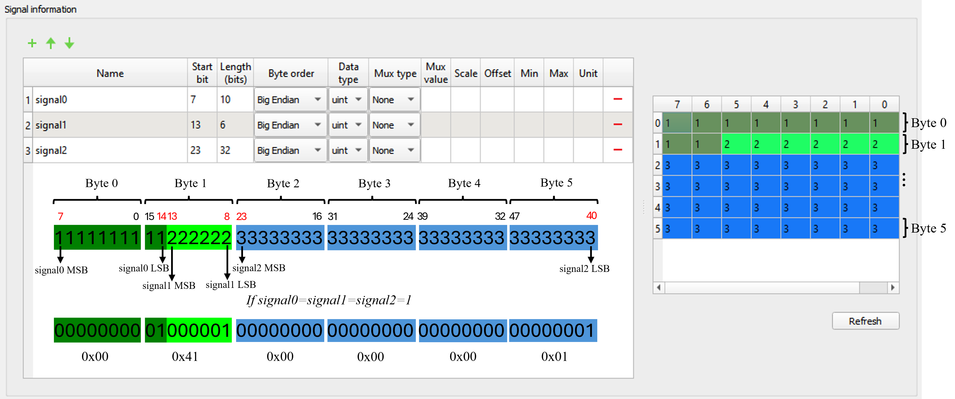
To be a professional firmware engineer, you must be able to write code that can reliably "unpack" these signals from the raw RxData array.
3. Techniques for Unpacking CAN Signals
Let's explore how to extract a specific signal from the RxData byte array. There are two common methods, but one is clearly superior in a professional context.
Method 1: Bitwise Operations (The Professional Standard)
This method uses bitwise masking (&) and shifting (>> or <<) to isolate and reassemble signals. It is the most robust, portable, and compiler-independent way to parse packed data.
How it works:
- Masking (
&): You use a bitmask to zero out all bits except the ones belonging to your signal of interest. - Shifting (
>>): You then right-shift the result to align the signal's least significant bit (LSB) to bit 0, turning it into a standard integer value.
Let's say we want to extract a 4-bit signal located in the upper nibble of RxData[2].
// RxData[2] contains our 4-bit signal in bits 7-4.
// For example, let's say RxData[2] = 0b1011xxxx, where '1011' is our signal.

// 1. Mask to isolate the upper 4 bits. The mask is 0xF0 (0b11110000).
uint8_t isolated_signal = RxData[2] & 0xF0; // Result: 0b10110000

// 2. Right-shift by 4 to move the signal to the LSB position.
uint8_t final_signal_value = isolated_signal >> 4; // Result: 0b00001011, which is 11 decimal.
This can be combined into a single, efficient line:uint8_t final_signal_value = (RxData[2] & 0xF0) >> 4;
This technique gives you complete, unambiguous control and works predictably on any C compiler and any MCU architecture.
Method 2: Unions with Bit-fields (The Non-Portable Shortcut)
Another method you might encounter uses a union containing a struct with bit-fields. The idea is to create a struct that mirrors the layout of the CAN payload and then use a union to overlay this struct onto the raw uint8_t RxData[8] array.
This approach seems neat, but it is highly non-portable and dangerous in professional development.
Extract bits and bytes from a CAN Bus message
This Stack Overflow discussion provides a perfect case study on this topic. It shows an example of the union/bit-field approach and includes a critical comment explaining its pitfalls.
First, look at the answer that starts with typedef union { struct { .... This shows the union/bit-field technique. Then, read the crucial comment below it by 'Robert'. He correctly points out that this code is non-portable due to compiler-specific structure padding, alignment, and endianness. This means the code might work with your specific compiler today but break unpredictably on a different compiler, with different optimization settings, or on a different MCU.
Because of these issues, you should always prefer bitwise operations for parsing CAN data in professional projects. It guarantees that your code is portable, maintainable, and free from subtle, compiler-dependent bugs.
4. Hands-On Implementation: Parsing a Live Message
Let's apply this knowledge. We will modify your project to send a message with a simple packed payload and then parse it in the receive callback.
Our Protocol:
- ID:
0x321 - DLC:
2 TxData[0]: A simple counter that increments with each message sent (0-255).TxData[1]: A status byte. We will use bit 0 as a command to control the LED.bit 0 = 1: Turn LED ON.bit 0 = 0: Turn LED OFF.
Step 1: Modify the Transmission Code
In your main.c, update the while(1) loop to prepare and send this new payload every second.
/* In main.c, inside the private variables section */
/* USER CODE BEGIN PV */
// ... your other variables ...
uint8_t counter = 0; // Add this counter
/* USER CODE END PV */


/* In main.c, inside the while(1) loop */
/* USER CODE BEGIN WHILE */
while (1)
{
    // Prepare the payload
    TxData[0] = counter; // Send the current counter value

    // Use the counter to toggle the LED command every second
    if (counter % 2 == 0) {
        TxData[1] = 0x01; // Command: LED ON (set bit 0)
    } else {
        TxData[1] = 0x00; // Command: LED OFF (clear bit 0)
    }

    // Set up the CAN message header
    TxHeader.StdId = 0x321;
    TxHeader.IDE = CAN_ID_STD;
    TxHeader.RTR = CAN_RTR_DATA;
    TxHeader.DLC = 2; // We are sending 2 bytes

    // Transmit the message
    if (HAL_CAN_AddTxMessage(&hcan, &TxHeader, TxData, &TxMailbox) != HAL_OK)
    {
      Error_Handler();
    }

    counter++; // Increment the counter for the next message

    HAL_Delay(1000); // Wait 1 second

    /* USER CODE END WHILE */
    /* USER CODE BEGIN 3 */
}
/* USER CODE END 3 */
Step 2: Modify the Receive Callback to Parse the Message
Now, update your HAL_CAN_RxFifo0MsgPendingCallback function. Instead of just toggling the LED, we will parse the payload and act on the command.
/* In main.c, add a global variable to inspect the counter in the debugger */
/* USER CODE BEGIN PV */
// ... your other variables ...
uint8_t counter = 0;
volatile uint8_t received_counter = 0; // 'volatile' to prevent optimization
/* USER CODE END PV */


/* In main.c, inside the USER CODE 4 section */
/* USER CODE BEGIN 4 */

void HAL_CAN_RxFifo0MsgPendingCallback(CAN_HandleTypeDef *hcan)
{
    // Retrieve the message from FIFO 0
    if (HAL_CAN_GetRxMessage(hcan, CAN_RX_FIFO0, &RxHeader, RxData) == HAL_OK)
    {
        // 1. Check if the message is the one we expect (ID and length)
        if ((RxHeader.StdId == 0x321) && (RxHeader.DLC == 2))
        {
            // 2. Parse the payload

            // Store the counter value for debugging
            received_counter = RxData[0];

            // Extract the LED command from bit 0 of the status byte
            uint8_t led_command = RxData[1] & 0x01; // Mask to get only bit 0

            // 3. Act on the parsed data
            if (led_command == 1)
            {
                // The onboard LED on Blue Pill is active-low, so set LOW to turn ON.
                HAL_GPIO_WritePin(GPIOC, GPIO_PIN_13, GPIO_PIN_RESET); // LED ON
            }
            else
            {
                HAL_GPIO_WritePin(GPIOC, GPIO_PIN_13, GPIO_PIN_SET); // LED OFF
            }
        }
    }
}

/* USER CODE END 4 */
Step 3: Build, Flash, and Debug
- Compile and flash the updated code to your Blue Pill board.
- The board will send a CAN message to itself every second.
- The receive interrupt will fire, and your callback will parse the payload.
- You should now see the onboard LED (PC13) turn on for one second, then off for one second, matching the command sent in
TxData[1]. - For an extra step, start a debug session, pause the execution, and inspect the
received_countervariable. You will see it updating with the value fromRxData[0], confirming you are successfully parsing that byte as well.
Conclusion
Excellent work! You have now mastered the fundamental skill of parsing CAN messages. You can confidently extract the sender's ID, check the data length, and use robust bitwise operations to unpack signals from the raw payload. This moves you from simply detecting communication to understanding and acting upon it, a critical capability for any embedded systems engineer.
Key Takeaways:
HAL_CAN_GetRxMessage()populates theRxHeader(metadata) andRxData(payload) structures.- Always check
RxHeader.DLCto know how many bytes of the payload are valid. - CAN payloads often contain multiple signals packed into the bits of the 8-byte data field.
- Bitwise masking (
&) and shifting (>>) is the professional, portable, and reliable method for unpacking these signals. - Avoid using unions with bit-fields for parsing due to non-portable, compiler-dependent behavior.
In our previous lessons, we've focused on a single board talking to itself. To truly test our CAN communication stack, we need another node. In the next lesson, we will put everything together and build a two-node CAN bus demo, which is the final step in this module before we move on to building larger projects.