Welcome back. In our previous lesson, you successfully wrote the code to transmit a CAN message onto the bus. Your STM32 board is now broadcasting a message with a specific ID, but this is only half of the communication process.
A CAN bus is a shared medium, meaning every node sees every message transmitted. If a node had to process every single message in software just to see if it was relevant, the CPU would be quickly overwhelmed. This is a critical problem in automotive systems where hundreds or thousands of messages can be present on the bus every second.
This lesson addresses that exact problem. Our learning outcome is to configure CAN acceptance filters to receive specific message IDs. You will learn how to leverage the powerful hardware filtering capabilities of the STM32's bxCAN peripheral. This allows the microcontroller to automatically ignore irrelevant messages at the hardware level, saving CPU cycles and ensuring your application only gets interrupted when a message it cares about arrives.
1. The Principle of Hardware Filtering
The core idea behind CAN filtering is to offload the task of ID-checking from the software to the dedicated CAN peripheral hardware. You define a set of rules, and the hardware applies these rules to every incoming message. Only messages that pass the filter are accepted and placed into a receive buffer (a FIFO).
The STM32's bxCAN peripheral provides a number of filter banks (14 on the STM32F103) that you can configure. Each filter bank can be set up in one of two primary modes:
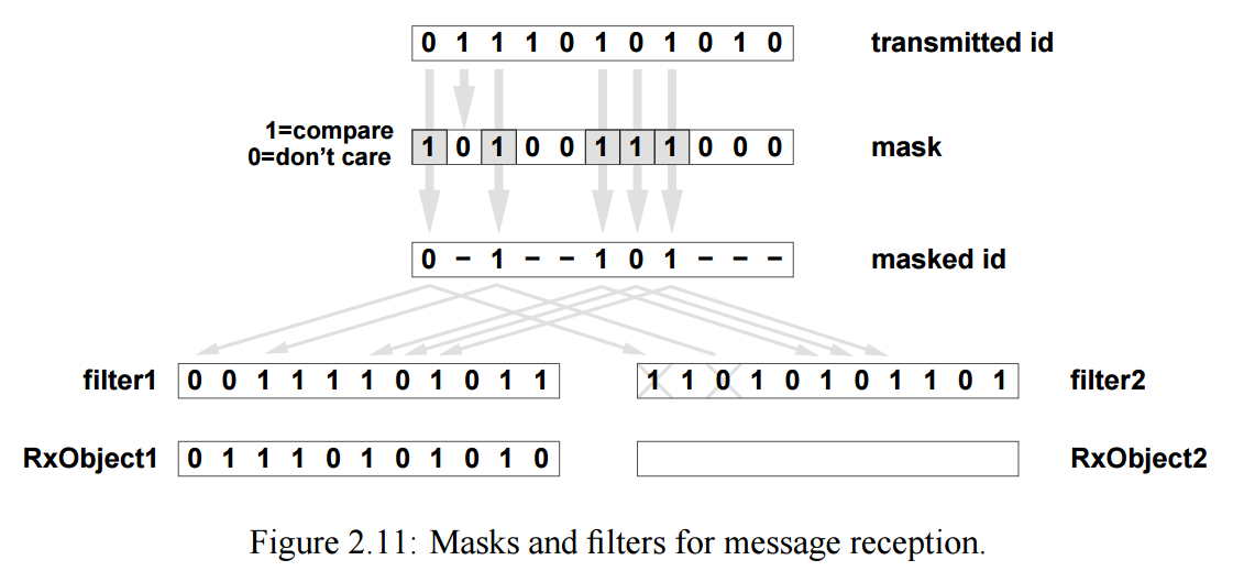
- Identifier Mask Mode: This is the most flexible and commonly used mode. You provide two values: an Identifier and a Mask. The hardware performs a bitwise comparison. For every bit set to '1' in the mask, the corresponding bit in the incoming message's ID must match the corresponding bit in the filter's Identifier. If a bit in the mask is '0', the corresponding bit in the incoming ID is ignored ("don't care").
- Identifier List Mode: This mode is simpler. You provide a list of specific IDs. An incoming message is accepted only if its ID perfectly matches one of the IDs in the list.
The diagram below illustrates the logic of Mask Mode.
To get a solid grasp of these two modes and their practical applications, the following video provides an excellent conceptual breakdown.
Controller Area Network(CAN) programming Tutorial 19 : bxCAN acceptance filtering
This video from Fastbit Embedded Brain Academy explains the theory behind CAN acceptance filtering. It provides clear examples for both Mask Mode and List Mode.
Watch the following segments: 00:00 - 04:21: Focus on the explanation of filter banks and how Mask Mode works using the ID and Mask registers. The examples clearly show how to build a filter rule. 04:21 - 08:34: Pay attention to the explanation of Identifier List Mode and how it differs from Mask Mode. This will help you understand when to use each one.
2. Configuring a Filter with the HAL Library
Now that you understand the concepts, let's translate them into code using the STM32 HAL. The configuration is handled through a struct called CAN_FilterTypeDef.
This article provides a very clear, practical example of setting up this struct.
STM32 CAN Bus Communication Tutorial (Normal Mode)
This tutorial from ControllersTech demonstrates the practical steps for setting up a CAN filter using the HAL library. It provides a clean code snippet that we will adapt for our project.
Read the section titled "Configuring CAN Filters in STM32". Focus on the CAN_FilterTypeDef struct and the explanation of its members like FilterBank, FilterMode, FilterIdHigh, and FilterMaskIdHigh. This is exactly what we need to implement.
As you saw in the article, we need to populate this struct and then pass it to the HAL_CAN_ConfigFilter() function. The most complex part is setting the ID and Mask values correctly, as they need to be bit-shifted to fit into the filter registers.
Understanding the Filter Registers
The filter banks use two 32-bit registers, CAN_FxR1 and CAN_FxR2. When using a 32-bit filter scale for a standard 11-bit ID, the ID bits (STID[10:0]), the IDE (Identifier Extension) bit, and the RTR (Remote Transmission Request) bit are mapped to the upper part of the first register (CAN_FxR1).

Based on the register map, the 11-bit Standard ID (STID[10:0]) occupies bits [31:21] of the 32-bit filter register. To place our 11-bit ID in this position, we need to left-shift it. The HAL library simplifies this: you only need to left-shift the ID and mask by 5 bits when assigning them to the FilterIdHigh and FilterMaskIdHigh fields of the 16-bit register view.
Let's look at two examples for an 11-bit standard ID:
Example 1: Accept only ID 0x456
- Filter ID:
0x456 - Filter Mask:
0x7FF(binary111 1111 1111). This mask says that all 11 bits of the incoming ID must match the filter ID. - Code:
sFilterConfig.FilterIdHigh = (0x456 << 5);
sFilterConfig.FilterMaskIdHigh = (0x7FF << 5);
Example 2: Accept all IDs from 0x450 to 0x45F
- Filter ID:
0x450. We set the base ID we want to match. - Filter Mask:
0x7F0. The last 4 bits of the mask are0, so they are "don't care," while the upper 7 bits must match0x450. - Code:
sFilterConfig.FilterIdHigh = (0x450 << 5);
sFilterConfig.FilterMaskIdHigh = (0x7F0 << 5);
3. Hands-On Implementation
It's time to add a filter to your project. We will configure your board to accept messages with the ID 0x321.
-
Open your project in STM32CubeIDE.
-
Declare and configure the filter: In
main.c, inside themain()function but before thewhile(1)loop, add the following code block. Place it afterMX_CAN_Init()and beforeHAL_CAN_Start()./* USER CODE BEGIN 2 */ // Previous HAL_CAN_Start() call should be moved after this CAN_FilterTypeDef sFilterConfig; sFilterConfig.FilterBank = 0; // Use filter bank 0 sFilterConfig.FilterMode = CAN_FILTERMODE_IDMASK; // Use Identifier Mask mode sFilterConfig.FilterScale = CAN_FILTERSCALE_32BIT; // Set filter scale to 32-bit sFilterConfig.FilterIdHigh = (0x321 << 5); // ID to accept sFilterConfig.FilterIdLow = 0x0000; sFilterConfig.FilterMaskIdHigh = (0x7FF << 5); // Mask: all 11 bits must match sFilterConfig.FilterMaskIdLow = 0x0000; sFilterConfig.FilterFIFOAssignment = CAN_RX_FIFO0; // Assign to FIFO 0 sFilterConfig.FilterActivation = ENABLE; // Enable the filter sFilterConfig.SlaveStartFilterBank = 14; // For single CAN devices, this is not critical if (HAL_CAN_ConfigFilter(&hcan, &sFilterConfig) != HAL_OK) { /* Filter configuration Error */ Error_Handler(); } // Now start the CAN peripheral if (HAL_CAN_Start(&hcan) != HAL_OK) { /* Start Error */ Error_Handler(); } /* USER CODE END 2 */Note: Ensure the
HAL_CAN_Start(&hcan)call you added in the previous lesson is placed after this filter configuration block. -
Update the transmit ID: Your previous code was transmitting ID
0x123. The filter we just configured is looking for0x321. To test our complete system later, let's make the transmitter send the ID our filter is expecting. Find thewhile(1)loop and change theTxHeader.StdIdline:/* Infinite loop */ /* USER CODE BEGIN WHILE */ while (1) { // Configure the header TxHeader.StdId = 0x321; // <<< CHANGE THIS LINE TxHeader.IDE = CAN_ID_STD; // ... rest of the transmit code -
Compile and Flash: Build and flash the updated code to your board.
Your microcontroller is now transmitting a message with ID 0x321 every second, and its own CAN peripheral is configured to accept only messages with that specific ID. Any other messages on the bus will be ignored by the hardware.
Conclusion
Excellent work. You have now mastered a fundamental technique for building robust and efficient CAN nodes. By configuring hardware acceptance filters, you ensure that your firmware only spends time processing messages that are directly relevant to its function.
Key Takeaways:
- CAN hardware filters are crucial for reducing CPU load in a busy network.
- The two main filtering modes are Identifier Mask Mode (for flexible pattern matching) and Identifier List Mode (for matching exact IDs).
- In STM32 HAL, filter rules are defined in a
CAN_FilterTypeDefstruct and applied withHAL_CAN_ConfigFilter(). - The most critical step is correctly bit-shifting the ID and Mask values to align them within the hardware filter registers. For standard 11-bit IDs, this involves a left-shift by 5 into the
FilterIdHighandFilterMaskIdHighfields.
Our node is now transmitting a specific message and is configured to listen for it. However, we haven't written any code to actually do something when the message is received. In our next lesson, you will learn how to set up a CAN receive interrupt, which will trigger a function in your code the moment a filtered message arrives in the receive FIFO.